CASSETTI TRADIZIONALI E CODE DI RONDINE SEMINASCOSTE / TRADITIONAL DRAWERS AND HALF LAP DOVETAILS
English translation at the end of the article
Le giunzioni dei primi manufatti in legno si basavano essenzialmente sulla tenuta di chiodi, perni, cunei e colle di origine animale. Tali elementi non erano però in grado di assicurare una durevole stabilità del manufatto. I chiodi infatti finivano per fessurare il legno e presto si arrugginivano mentre le colle animali non garantivano la necessaria tenuta nel tempo. Fu solo nel Medioevo che diventarono di largo impiego i sistemi di giunzione a mezzo incastro, primo fra tutti il sistema a tenone e mortasa. Oltre a questo, nel XV secolo, conobbe una forte espansione anche la tecnica dell’incastro a coda di rondine che riuscì ad apportare la necessaria robustezza alle giunzioni angolari oltre a donare quel tocco di bellezza tanto in voga nell’epoca rinascimentale.
Oggigiorno, lungi dall’essere un mero esercizio di stile, gli incastri a coda di rondine sono non solo sinonimo di pregio ed eleganza ma anche di solidità. Tra le varie tipologie di incastri sono sicuramente quelli più difficili da realizzare e per i quali è necessaria una certa pratica al fine di riuscire a padroneggiarne l’esecuzione. Per un approfondimento sulla tecnica di realizzazione delle code di rondine a vista vi rimando al seguente link
Gli incastri. Come fare l’incastro a coda di rondine. The joints. How to make the dovetail joint.
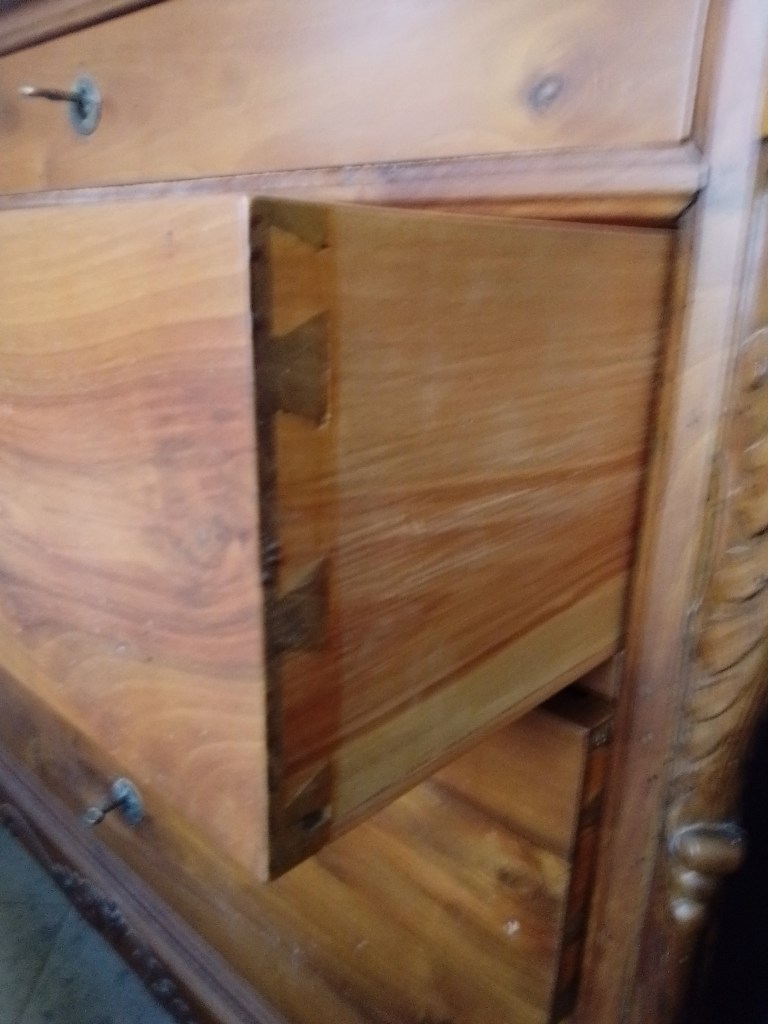
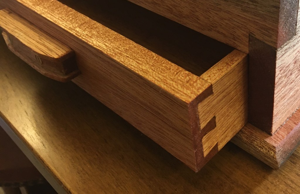
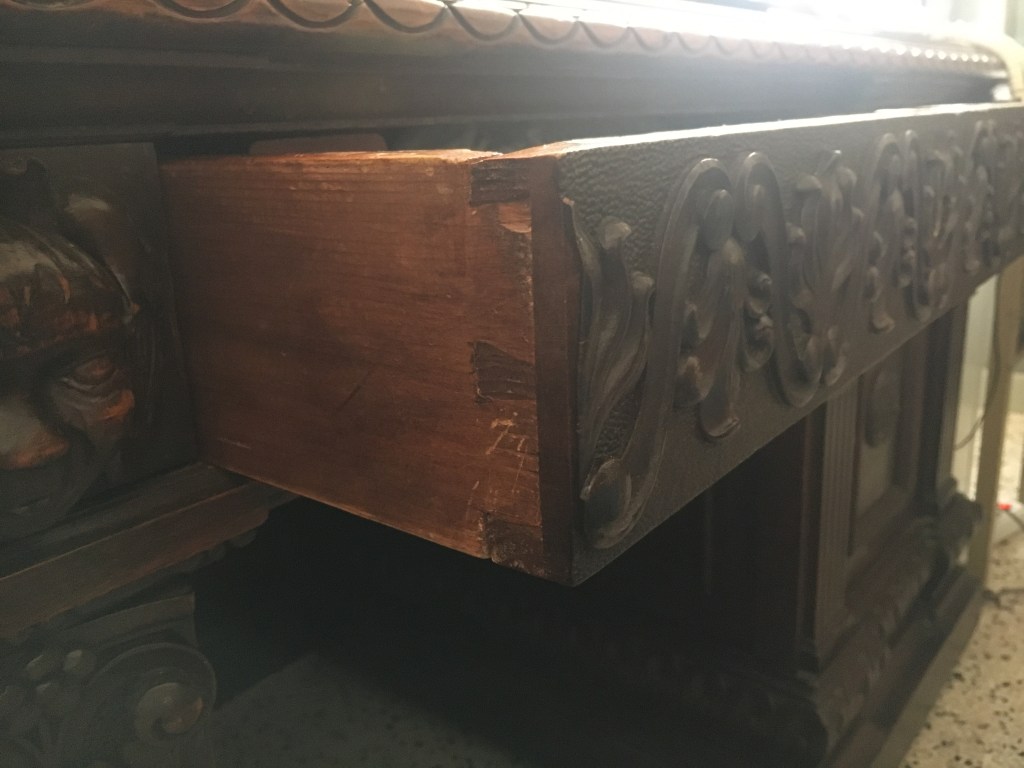
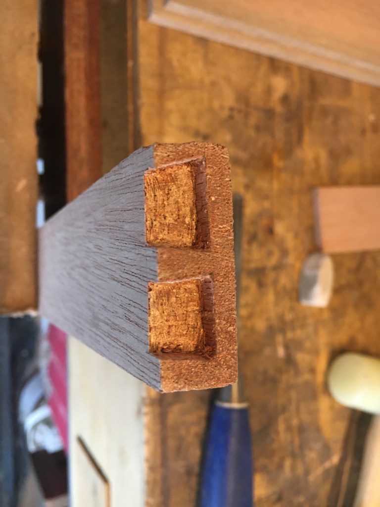
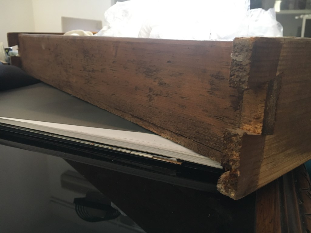
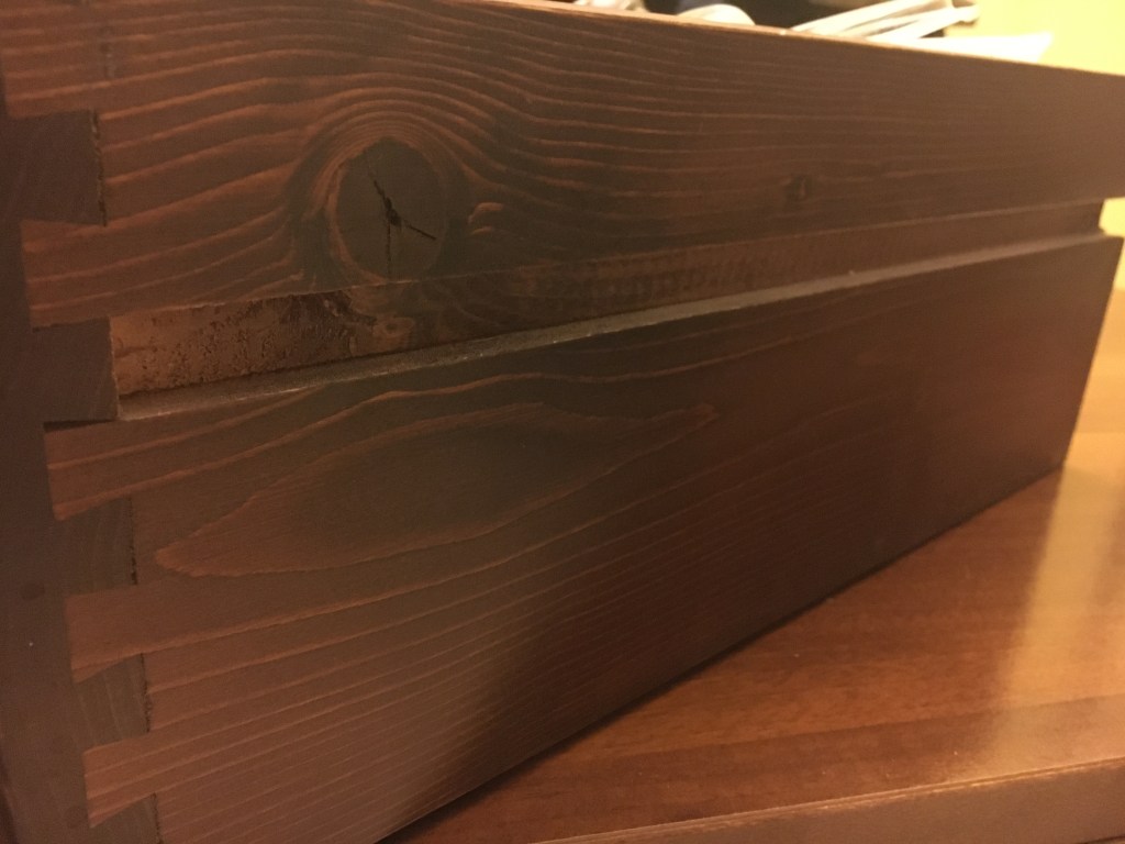
In questo post volevo invece soffermarmi su una particolare tipologia di incastro a coda di rondine: la coda di rondine seminascosta. Come si evince dal nome in questo tipo di incastro le code di rondine sono visibili solo su un fianco di un pezzo mentre sull’altro rimangono nascoste perché ricomprese nello spessore. Questo è possibile in quanto le code sono fatte più corte rispetto allo spessore del pezzo ricevente. Il classico esempio di questo tipo di giunzione è riscontrabile nella realizzazione degli incastri angolari dei cassetti nella falegnameria classica amanuense ed è proprio in tale ambito che hanno trovato (ed ancor oggi trovano) il loro maggior impiego. Infatti, mentre gli elementi dei cassetti moderni sono semplicemente incollati tra loro senza alcun tipo di incastro e le code di rondine, se presenti, sono probabilmente fatte con l’ausilio di macchinari, così come anche le guide di scorrimento sono elementi aggiunti in metallo, al contrario in tutti i mobili d’epoca i cassetti presentavano sempre le code di rondine seminascoste che, realizzate a mano da artigiani esperti, garantivano la necessaria resistenza alle sollecitazioni ai quali venivano continuamente sottoposti nel loro movimento di apertura e chiusura.

Le code di rondine seminascoste sono visibili sui fianchi e nascoste sul frontale mentre l’unione del retro del cassetto ai laterali è fatta a tenone e mortasa, a dente e canale oppure a coda di rondine a vista. Nei fianchi e nel frontale, all’altezza dello zoccolo più basso, viene praticata una scanalatura che accoglie il fondo del cassetto, solitamente in multistrato o in legno massello.
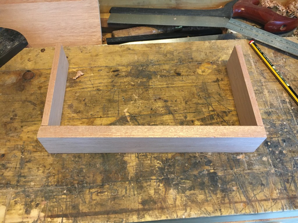
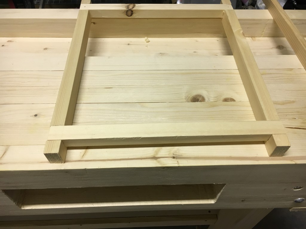
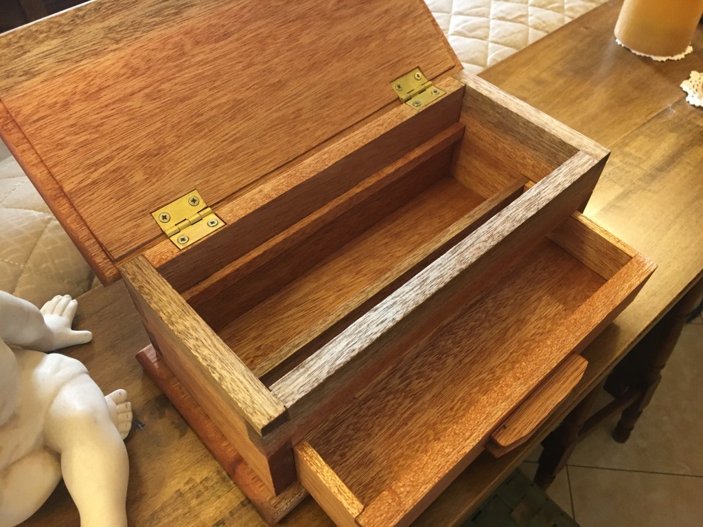
La costruzione di un cassetto segue delle regole ben precise che, con qualche lieve adattamento, possono essere riassunte come segue (le foto sono tratte da due lavori distinti e separati, un cassettino per una scatola ed il cassetto del mio banco). Cominciando dalla preparazione dei pezzi, le coste e le facce di ogni elemento vanno piallate in modo da rendere le superfici perfettamente perpendicolari tra loro. I due laterali dovranno avere la stessa lunghezza ed altezza mentre il retro sarà di 2 mm. più corto rispetto al frontale così da facilitare l’entrata del cassetto nella sua sede. Anche l’altezza dei pezzi dovrà essere uguale, sempre fatta eccezione per il retro, che sarà più basso a seconda del tipo di incastro che utilizzeremo per inserire il fondo del cassetto. Normalmente lo spessore dei laterali e del retro varia tra i 6 mm. e gli 1,5 cm. mentre il frontale tra gli 1,5 cm. e i 2,2 cm. La regola vorrebbe che maggiori sono le dimensioni del cassetto maggiore dovrebbe essere lo spessore dei pezzi. Il frontale dovrebbe comunque avere sempre uno spessore maggiore di almeno 6 mm. rispetto a quello dei pezzi laterali.
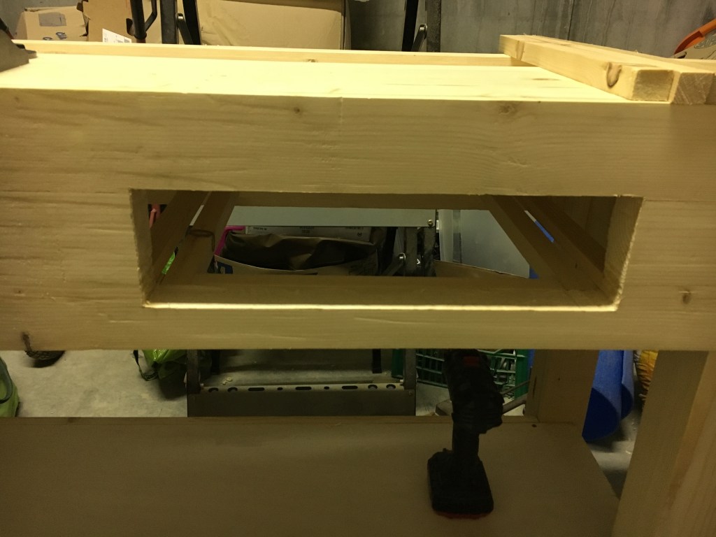
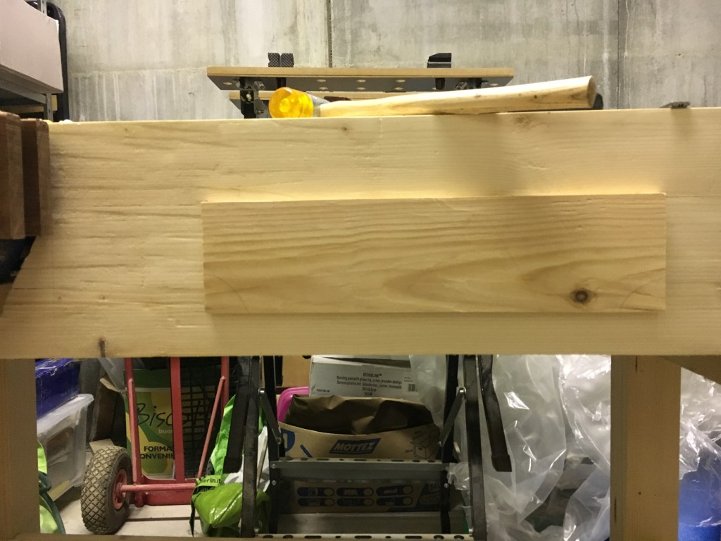
Per adattare il cassetto alla misura dell’alloggiamento del mobile dobbiamo per prima cosa rifinire con la pialla tutte le coste del frontale del cassetto. Pialliamo prima la parte inferiore, poi le coste adiacenti ed infine la parte superiore sino a quando il frontale non si incastrerà nella carcassa, forzando leggermente, e senza lasciare spazi vuoti. Il frontale verrà poi rifinito successivamente, una volta terminati gli incastri e fatto l’incollaggio. Seguiamo lo stesso ordine di piallatura anche per i due laterali e per il retro, questa volta facendo in modo che riescano a scorrere all’interno della carcassa.
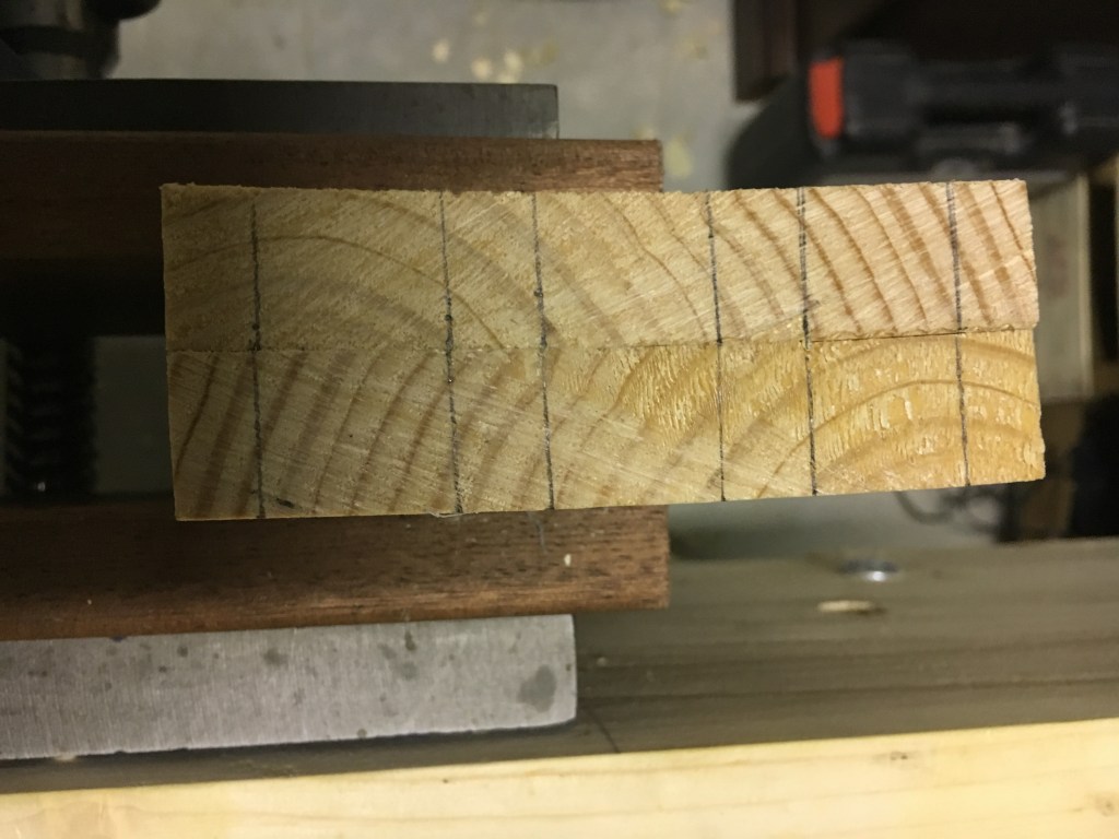
Tracciamo quindi a matita sui fianchi e sul frontale la traccia della scanalatura che accoglierà il fondo del cassetto e che andremo a praticare successivamente con l’incorsatoio. La scanalatura va praticata all’altezza dell’ultimo zoccolo del frontale in modo che il canale, una volta creato, rimanga nascosto dall’incastro ultimato. La larghezza della scanalatura sarà di qualche decimo di millimetro maggiore rispetto allo spessore del materiale che utilizzeremo per il fondo. Anche la profondità del canale dovrebbe essere di qualche decimo di millimetro superiore a quella definitiva ma questo dipenderà anche dallo spessore del pezzo (ad esempio in uno spessore di 1,5 cm. o superiore, 6 mm. di profondità del canale sono sufficienti). In questo modo lasceremo un minimo di spazio utile a consentire i movimenti stagionali e di acclimatazione del legno.
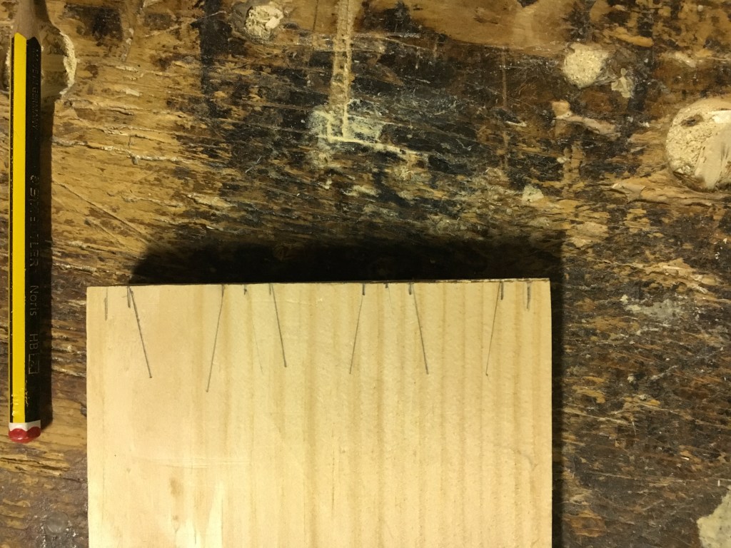
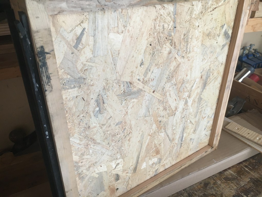
Per il fondo dei cassetti è molto utilizzato il multistrato da 5 o 6 mm. Non è comunque consigliabile scendere al di sotto di tale misura per non indebolire troppo la base. Al posto del multistrato è possibile impiegare anche il legno massello, o addirittura OSB (come nel cassetto del mio banco) ma nel caso del massello bisognerebbe orientare le fibre del legno del pannello in modo che siano parallele al frontale del cassetto, per ovviare ai movimenti di ritiro del legno. Come detto, le code di rondine sono più corte rispetto allo spessore del frontale, così da rimanere nascoste. Ad esempio, se lo spessore del frontale fosse di circa 2 cm. potremmo fare delle code di rondine lunghe 1,4 cm. così da lasciare 6 mm. di spazio tra queste ed il bordo del frontale. Lasciare spessori inferiori ai 6 mm. esporrebbe al rischio di rottura del frontale durante la lavorazione. Il numero di code da tracciare dipenderà dalla larghezza dei pezzi. Ad esempio, per un pezzo largo 10 cm., potremmo effettuare 3 code di rondine.
Le code di rondine vanno praticate sui laterali del cassetto. Con una matita ben appuntita tracciamo sul primo laterale la sagoma delle code aiutandoci con una falsa squadra o con l’apposita guida e poi trasferiamo le stesse tracce sull’altro laterale così da ottenere un perfetto parallelismo tra i fianchi. Per vedere come tracciare le code vi rimando al link sulle code di rondine segnalato sopra.

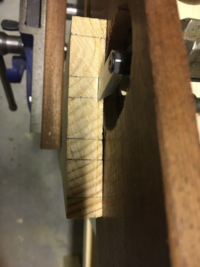
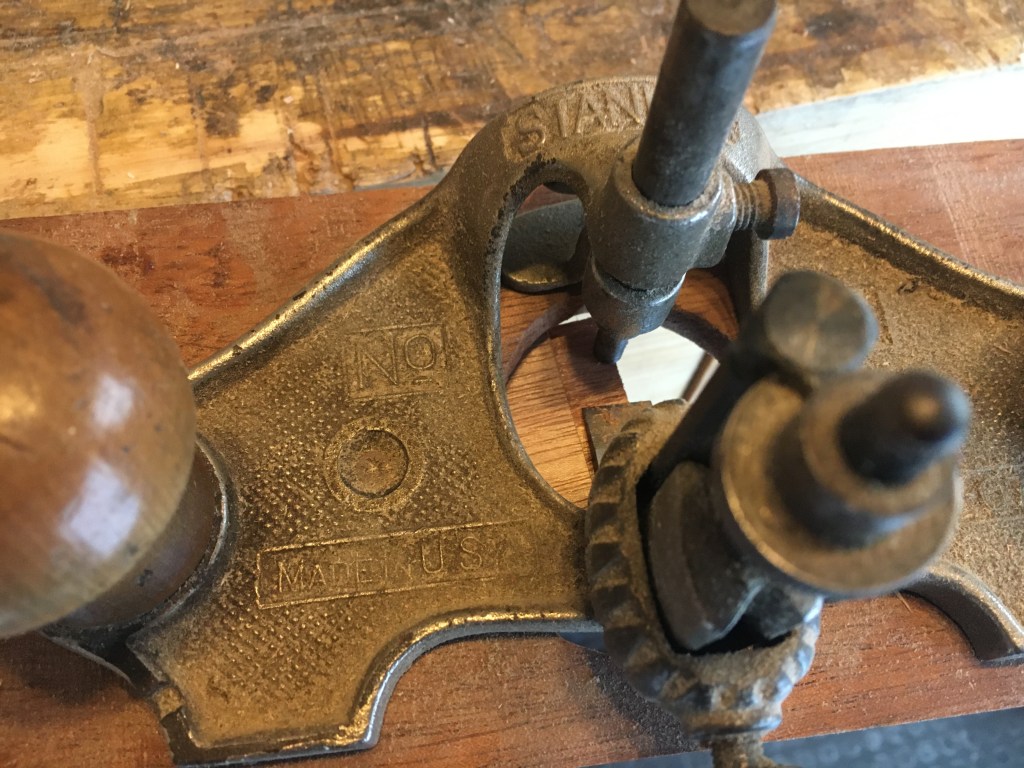
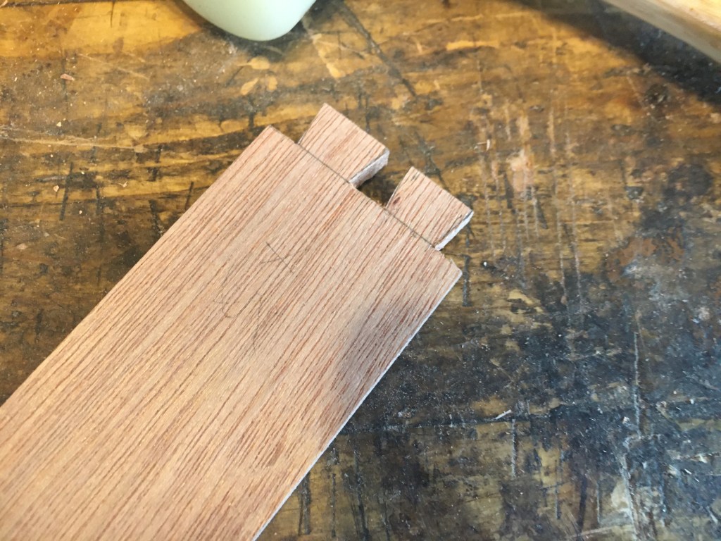
A questo punto possiamo procedere con il metodo classico oppure optare, come faccio io, per l’introduzione di una piccola variante, usata da Paul Sellers il quale, allo scopo di rendere più agevole la successiva tracciatura delle mortase sul frontale, pratica con la router plane, usata come un truschino un knifewall che poi rifinisce con gli scalpelli e la stessa router plane fino a ottenere uno scalino di 1,5 mm. sul retro dei pezzi laterali e per tutta la loro larghezza. Nelle foto evidenzio questo passaggio che potrebbe comunque anche essere saltato in quanto non determinante ai fini della riuscita dell’incastro.
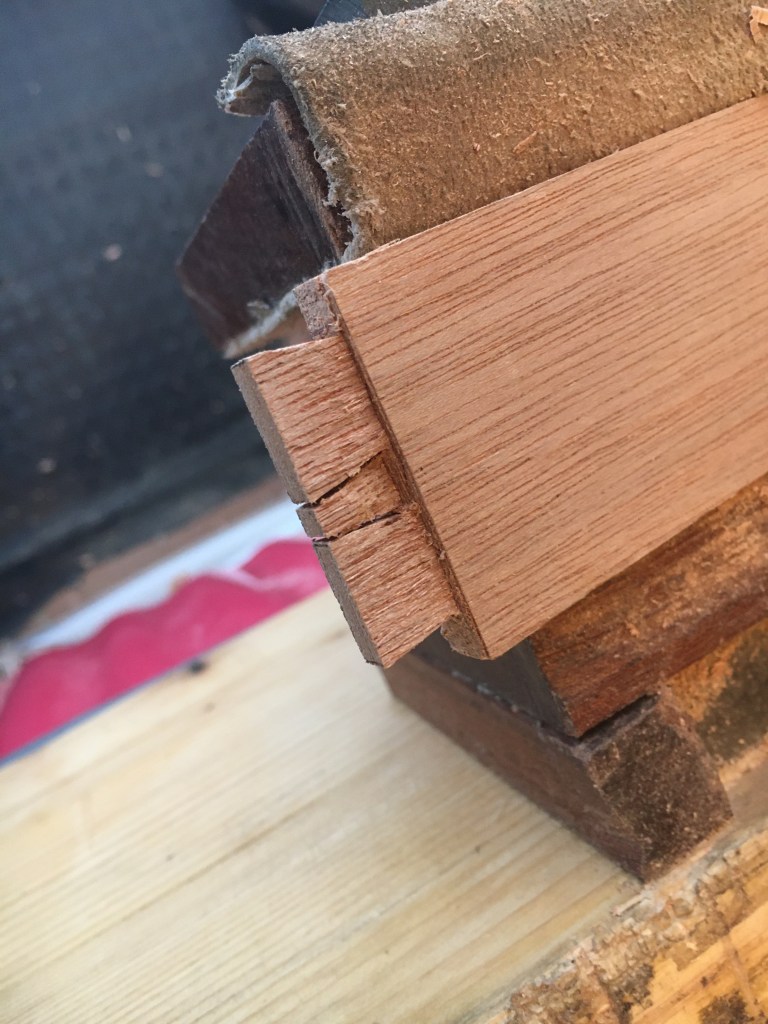
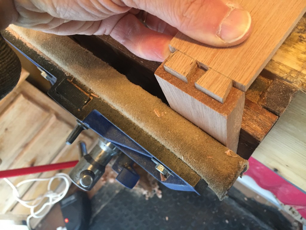
Seghiamo quindi le code di rondine sui laterali con l’ausilio di una sega per incastri e rimuoviamo con lo scalpello il materiale tra le code quindi riportiamo le misure delle code sul frontale con un coltellino da tracciatura (la procedura di appoggio del laterale al frontale è facilitata se abbiamo praticato lo scalino di cui sopra). Sempre sul frontale riportiamo anche la profondità delle code con la misura presa ponendo direttamente le stesse sul pezzo frontale.
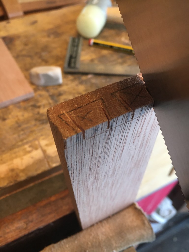
Infine, con la sega per incastri, seghiamo da angolo ad angolo i limiti delle mortase (c.d. zoccoli) che accoglieranno le code, mantenendoci a circa un millimetro dalla traccia. Durante l’azione teniamo la sega inclinata e facciamo attenzione a non oltrepassare le tracce. Infine procediamo a scavare le mortase con gli scalpelli, utilizzando quelli più stretti per pulire gli angoli altrimenti difficili da raggiungere. Procediamo sempre per gradi, avvicinandoci alle tracce fatte con il coltellino eliminando poco materiale alla volta, praticando poca forza sugli scalpelli per non correre il rischio di rompere il frontale e sino a quando non saremo arrivati esattamente sulle tracce.
Infine proviamo l’incastro, che non dovrà essere ne troppo stretto ne troppo lasco. Tra le due opzioni è sicuramente preferibile la prima in quanto potremo intervenire sulle code o nelle mortase rifinendo quei punti dove il legno è più lucido a causa dell’attrito. Possiamo eventualmente fare anche delle incisioni sugli spigoli interni delle code per agevolarne l’inserimento. L’incastro lasco costringerebbe invece ad inserire degli spessori che risulterebbero comunque visibili esternamente. Ripetiamo la stessa procedura anche per il secondo laterale.
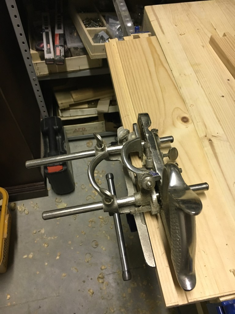
Il prossimo passaggio è quello di creare la scanalatura per l’inserimento del fondo del cassetto. Come detto, avevamo già segnato a matita dove praticare questo canale. Nel frontale la scanalatura deve essere fatta all’altezza della parte inferiore della mortasa ed essere ricompresa in essa perché verrà poi nascosta dalla coda di rondine. Se ricadesse nel piede del frontale si vedrebbe esternamente. Nei laterali la scanalatura ricadrà invece all’interno del pezzo e nascosta dall’incastro e quindi non visibile esternamente. Utilizziamo l’incorsatoio inserendo una lama preferibilmente di qualche decimo di millimetro più larga dello spessore del fondo ed impostiamo la misura della suoletta che limita la profondità a circa 6 mm. (che sarà quindi anche la profondità del canale). Per l’utilizzo dell’incorsatoio vi rimando al link sotto.
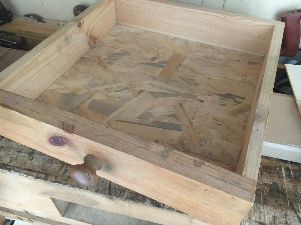
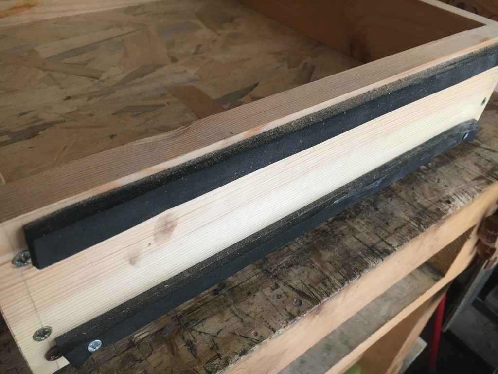
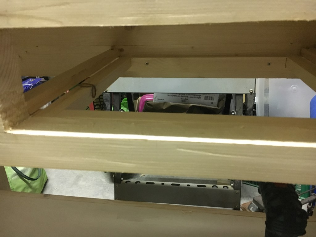
Esistono svariati sistemi per inserire il fondo del cassetto. Tra i più usati, oltre a quello dell’inserimento del fondo in una scanalatura, c’è anche quello di creare degli appositi sostegni interni (come nel caso del cassettino della mia scatola), oppure incollare internamente dei listelli nei quali inserire successivamente il fondo dentro apposite scanalature. A seconda di come vorremo inserire il fondo cambierà anche il sistema di incastro del retro del cassetto. Se abbiamo optato per il metodo classico della scanalatura, il retro potrà essere unito ai laterali con un incastro dente e canale. In sostanza, lo spessore del retro del cassetto farà da dente e si inserirà nei canali praticati sui laterali, sino a raggiungere l’altezza della scanalatura nella quale si inserirà il fondo e che dovrà quindi rimanere libera. Il fondo infine potrà essere bloccato al retro del cassetto per mezzo di viti, senza essere incollato. Se il fondo è in multistrato potremo inserirlo senza particolari problemi. Se fosse in legno massello e di spessore consistente lo si può assottigliare sui fianchi creando una sorta di bugnatura. Per il cassetto del mio banco ho utilizzato un metodo ancora diverso: la scanalatura che ospita il fondo è stata praticata anche sul retro e quest’ultimo unito ai laterali con viti e infine provvisto di due guarnizioni in gomma per attutire gli urti.
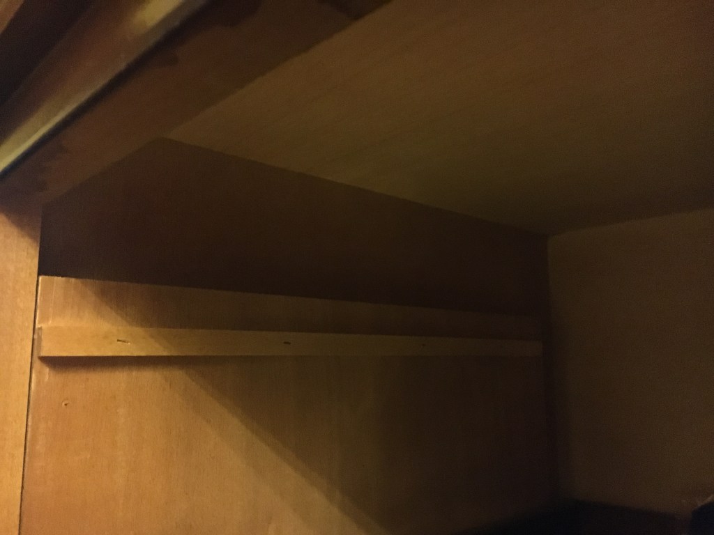
Se il cassetto è di grandi dimensioni è possibile anche aggiungere una traversa inferiore che, unita al frontale e al retro, apporti rigidità al fondo. Componiamo il cassetto inserendo anche il fondo e rifiniamolo piallando in quei punti dove fa attrito con la carcassa. In particolare dovremo riprendere il frontale, che avevamo lasciato da rifinire, e portarlo ad una misura tale che si crei qualche decimo di millimetro di spazio tra il cassetto e l’imboccatura. Lavoriamo sempre con particolare cura il frontale in quanto sarà la parte più in vista del cassetto.
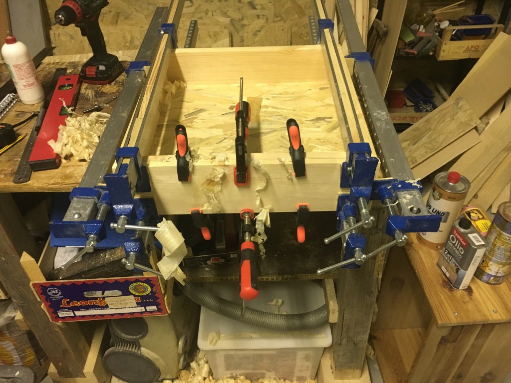
Prima di incollare facciamo una prova a secco unendo tutti i vari elementi e verifichiamo con un flessometro che le diagonali interne del cassetto siamo della stessa misura. Infine applichiamo la colla sulle code e nelle mortase e cominciamo a unire gli incastri partendo dai laterali con il frontale, poi inseriamo il fondo (senza incollare) e per ultimo il retro del cassetto. Quindi, prima di applicare i morsetti, ricontrolliamo con il flessometro le diagonali interne del cassetto ed eventualmente correggiamo il fuori squadro (sempre se minimo) applicando più pressione con i morsetti nei punti dove necessita.
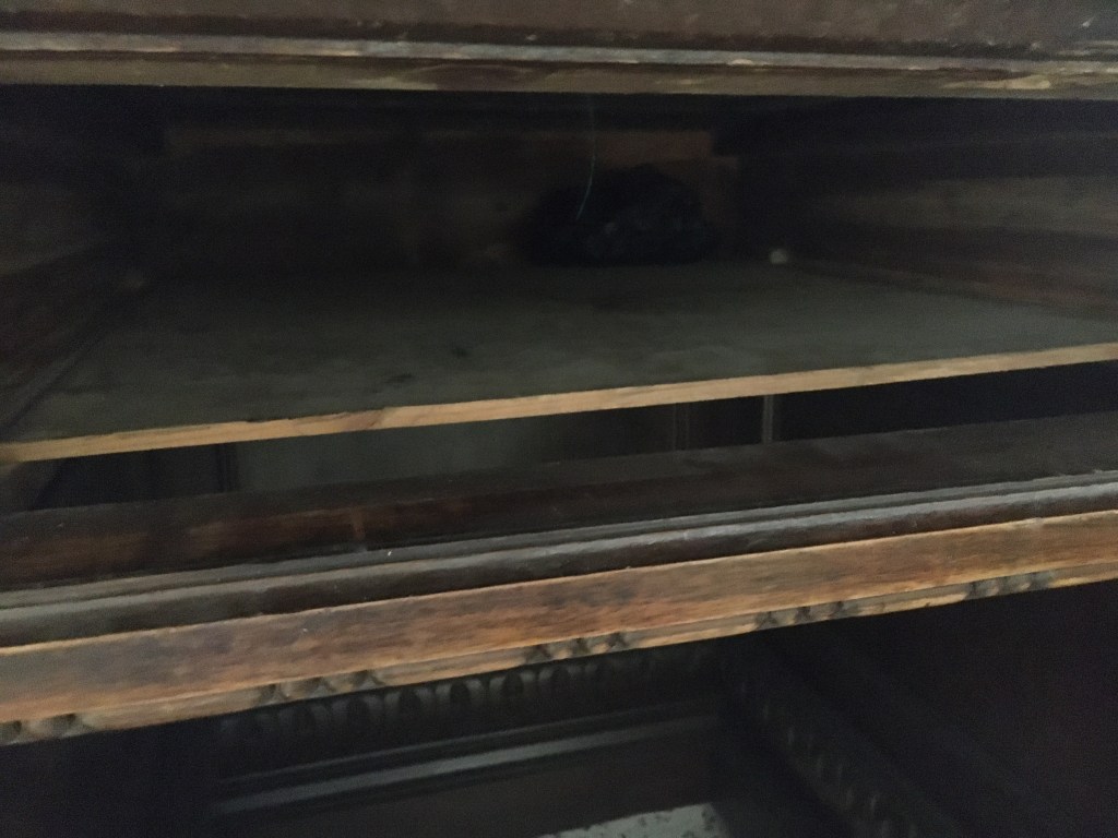
Un cassetto può essere costruito in modo che i fianchi sporgano dal retro di qualche centimetro, come solitamente veniva fatto nei cassettoni di una volta oppure mandarlo direttamente in battuta contro il fondo della carcassa o, se il cassetto fosse più corto, inserire degli arresti in legno sul fondo della carcassa, dove possa andare fermarsi.
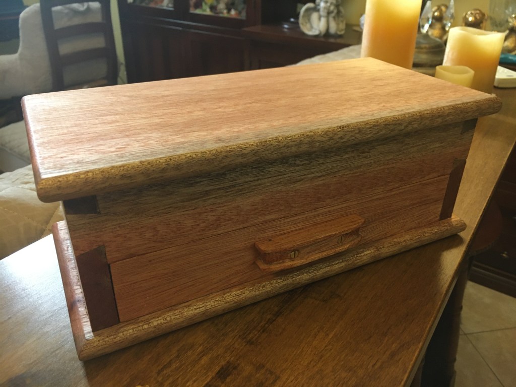
Possiamo anche prevedere una battuta nella parte superiore del frontale del cassetto in modo che questo si chiuda rimanendo sempre a filo con il fronte del mobile oppure applicare un frontale aggiuntivo, magari abbellito con delle modanature o dei fregi ornamentali.
Il cassetto può poggiare e quindi scorrere direttamente sul fondo del mobile oppure essere sospeso e scorrere su delle guide in legno inserite nella carcassa (e quindi il cassetto dovrà avere le opportune scanalature laterali), oppure con le guide inserite nei fianchi laterali del cassetto (e quindi le scanalature dovranno essere fatte nella carcassa del mobile) o, ancora, scorrere su appositi supporti. Lo scorrimento del cassetto potrà infine essere facilitato con l’applicazione di cera o sapone di Marsiglia.
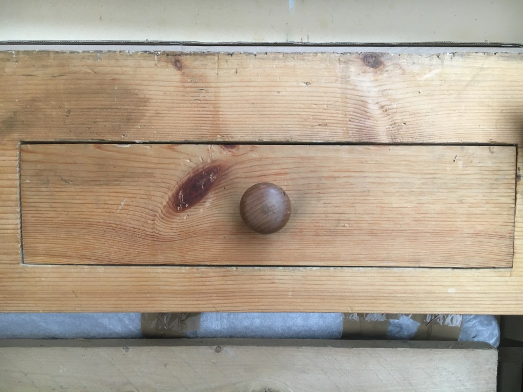
Come sistema di apertura potremo aggiungere uno o più pomelli o delle maniglie in legno o metallo oppure ricavare un’apertura direttamente nel frontale. Infine potremo dotarlo di una serratura a toppa con chiave.
Costruire un cassetto (e soprattutto una serie di cassetti) richiede tecnica, tempo e pazienza soprattutto se vogliamo attenerci ai canoni costruttivi della falegnameria amanuense. Bisogna squadrare perfettamente i vari elementi che lo compongono ma anche l’apertura che lo ospiterà, perché se questa non fosse in squadra il cassetto non potrebbe entrare. Occorre essere precisi anche nelle misurazioni e nell’esecuzione degli incastri. Valutare attentamente, in tutte le fasi di lavorazione, le interazioni tra i vari pezzi è fondamentale per evitare che un eventuale errore possa ripercuotersi sull’intero progetto.
____________________________________________________________________________________________________
The joints of the ancient furniturr were essentially based on nails, wedges and glues of animal origin. However, these elements were not able to ensure a lasting stability. The nails in fact ended up cracking the wood and soon rusted while the animal glues did not guarantee the necessary resistance over time. It was only in the Middle Ages that interlocking joining systems became widely used, first of all the mortise and tenon system. Apart from this, in the fifteenth century, the dovetail joint technique also experienced a strong expansion, which succeeded in bringing the necessary strength to the corner joints as well as giving that touch of beauty so much in vogue in the Renaissance era. Nowadays, far from being a mere exercise in style, dovetail joints are not only synonymous with value and elegance but also with solidity. Among the various types of joints they are certainly the most difficult to make and for which a certain practice is required in order to be able to master the execution. For more information on the technique of making visible dovetails, I refer you to the link above.
In this post, on the other hand, I wanted to focus on a particular type of dovetail joint: the half lap dovetail. As the name say, in this type of joint the dovetails are visible only on one side of a piece while on the other they remain hidden because they are included in the thickness. This is possible as the tails are made shorter than the thickness of the receiving piece. The classic example of this type of joint can be found in the making of the corner joints of the drawers in the classic woodworking by hand and it is precisely in this context that they have found (and still find today) their greatest use. In fact, while the elements of modern drawers are simply glued together without any kind of joint and the dovetails, if present, are probably made with the aid of machinery, as well as the sliding guides are added elements in metal, on the contrary, in all period furniture the drawers always had hal lap dovetails which, hand-made by expert craftsmen, guaranteed the necessary resistance to the stresses to which they were continually subjected in their opening and closing movement.
The half lap dovetails are visible on the sides and hidden on the front, while the joint of the back of the drawer to the sides is made by mortise and tenon joint, housing dadoes joint or dovetail joint. In the sides and front, at the height of the lowest pin a groove is made to accommodate the bottom of the drawer, usually in plywood or solid wood.
The making of a drawer follows very precise rules which, with some slight adaptation, can be summarized as follows (the photos are taken from two distinct and separate works, a drawer for a box and the drawer of my workbench ). Starting with the preparation of the pieces, the edges and faces of each element must be planed in order to make the surfaces perfectly perpendicular to each other. The two sides must have the same length and height while the back will be 2 mm. shorter than the front so as to facilitate the entry of the drawer into its seat. The height of the pieces must also be the same, always except for the back, which will be lower depending on the type of joint that we will use to insert the bottom of the drawer. Normally the thickness of the sides and the back varies between 6 mm. and the 1.5 cm. while the front between 1.5 cm. and the 2.2 cm. The rule would be that the larger the drawer size, the thicker the pieces should be. The front should however always have a thickness greater than at least 6 mm. compared to that of the side pieces.
To adapt the drawer to the size of the furniture housing, we must first finish with a plane all the edges of the drawer front. First plane the lower part, then the adjacent edges and finally the upper part until the front will fit into the carcass, forcing slightly, and without leaving empty spaces. The front will then be finished later, once the joints are finished and glued. We follow the same planing order also for the two sides and for the back, this time making sure that they are able to slide inside the carcass.
We then draw in pencil on the sides and on the front the trace of the groove that will accommodate the bottom of the drawer and that we are going to practice later with the plough plane. The groove must be made at the height of the last recess of the front so that the groove, once created, remains hidden by the completed joint. The width of the groove will be a few tenths of a millimeter greater than the thickness of the material we will use for the bottom. The depth of the channel should also be a few tenths of a millimeter higher than the final one but this will also depend on the thickness of the piece (for example in a thickness of 1.5 cm or more,a 6 mm. groove depth is sufficient). In this way we will leave a minimum of useful space to allow seasonal and acclimatization movements of the wood.
Usually, for the bottom a 5 or 6 mm. plywood is used. However, it is not advisable to go below this measure in order not to weaken the base too much. Instead of plywood it is also possible to use solid wood, or even OSB (as in the drawer of my workbench) but in the case of solid wood, the grain of the panel should be oriented so that they are parallel to the front of the drawer, to obviate the movements of wood shrinkage. As mentioned, the dovetails are shorter than the thickness of the front, so as to remain hidden. For example, if the thickness of the front was about 2 cm. we could make 1.4 cm. long dovetails so as to leave 6 mm. of space between these and the edge of the front. Leaving thicknesses less than 6 mm. it would expose the front to the risk of breaking during processing. The number of tails to be traced will depend on the width of the pieces. For example, for a 10 cm wide piece, we could make 3 dovetails.
The dovetails are made on the sides of the drawer. With a well-pointed pencil we trace the shape of the tails on the first side with the help of a sliding bevel or with a dovetail guide and then we transfer the same traces on the other side so as to obtain a perfect parallelism. To see how to trace the dovetails, I refer you to the link on the dovetails indicated above.
At this point we can proceed with the classic method or opt, as I do, for the introduction of a small variant, used by Paul Sellers who, in order to make the subsequent tracing of the mortises on the front easier, practice with the router plane ,used as a marking gauge a knifewall which then refines with chisels and the router plane itself to obtain a small rebate of 1.5 mm. on the back of the side pieces and across their entire width. In the photos I highlight this step which could however also be skipped as it is not decisive for the success of the joint.
We then saw the dovetails on the sides with the dovetail saw and we remove the material between the tails with the chisel and then we transfer the measurements of the tails on the front with a knife (the procedure of supporting the side to the front is facilitated if we have practiced the rebate). Also on the front we also transfer the depth of the tails with the measurement taken by placing them directly on the front piece.
Then , with the dovetail saw, we saw from corner to corner the limits of the recess that will accommodate the tails, keeping us about a millimeter from the trace. During the action we keep the saw at an angle and take care not to go beyond the trace. Next, we proceed to chop the mortises with chisels, using the narrower ones to clean the otherwise hard-to-reach corners. We always proceed step by step, approaching the traces made with the knife, eliminating a little material at a time, practicing little force on the chisels in order not to run the risk of breaking the front and until we arrive exactly on the traces.
Finally, try the joint, which must not be neither too tight nor too loose. Of the two options, the first is certainly preferable as we will be able to e work on the tails or in the mortises by refining those points where the wood is more shiny due to friction. We can possibly also make incisions on the internal edges of the tails to facilitate the joint. The loose joint would instead force the insertion of a small piece of wood that would still be visible externally. We repeat the same procedure also for the second side.
The next step is to create the groove for the bottom of the drawer. As mentioned, we had already marked in pencil where to practice this grove. Into the front the groove must be made at the height of the lower part of the recess and be included in it because it will then be hidden by the dovetail. If it fell back into the pin of the front it would be seen externally. On the sides, the groove will fall back inside the piece and hidden by the joint and therefore not visible externally. We use the plough plane with a blade preferably a few tenths of a millimeter wider than the thickness of the bottom and set the size of the depth to about 6 mm. (which will therefore also be the depth of the grove). For the use of the plough plane I refer you to the link above.
There are several ways to insert the bottom of the drawer. Among the most used, in addition to inserting the bottom in a groove, there is also that of creating special internal supports (as in the case of the drawer of my box), or glue inside the strips in which to subsequently insert the bottom inside special grooves. Depending on how we want to insert the bottom, the joint system of the back of the drawer will also change. If we have opted for the classic groove method, the back can be joined to the sides with a housing dado joint. Basically, the thickness of the back of the drawer will act as a tooth and will be inserted into the grooves made on the sides, until it reaches the height of the groove in which the bottom will be inserted and which must therefore remain free. Finally, the bottom can be locked to the back of the drawer by screws, without being glued. If the bottom is in plywood we can insert it without particular problems. If it were in solid wood and of consistent thickness, it can be planed on the sides by creating a chamfer. For the drawer of my workbench I used a different method: the groove that houses the bottom was also made on the back and then the back joined to the sides with screws and finally provided with two rubber gaskets to cushion shocks.
If the drawer is large, it is also possible to add a lower crosspiece which, combined with the front and back, brings rigidity to the bottom. Once all the joints are sested and with the bottom inserted, we finish the drawer by planing in those points where it friction. In particular, we will have to plane the front, which we had left to finish, and bring it to such a size that a few tenths of a millimeter of space is created between the drawer and the opening. We always work the front with particular care as it will be the most visible part of the drawer.
Before gluing, we do a dry test by joining all the various elements without the glue and check with a tape measure that the internal diagonals of the drawer are the same size. Finally, we apply the glue on the tails and in the mortises and we begin to join starting from the sides with the front, then we insert the bottom (without gluing) and finally the back of the drawer. So, before applying the clamps, we recheck the internal diagonals of the drawer with the tape measure and eventually correct the out of square (always if minimum) by applying more pressure with the clamps in the points where it is needed. A drawer can be built so that the sides protrude from the back by a few centimeters, as was usually done in the drawers of the past or send it directly against the bottom or, if the drawer is shorter, insert wooden stops. at the bottom of the carcass, where it can go stop. We can also provide a stop in the upper part of the drawer front so that it closes always remaining flush with the front of the cabinet or apply an additional front, perhaps embellished with moldings or ornamental friezes.
The drawer can rest and then slide directly on the bottom of the cabinet or be suspended and slide on wooden guides inserted in the casing (and therefore the drawer must have the appropriate lateral grooves), or with the guides inserted in the lateral sides of the drawer (and then the grooves must be made in the furniture) or, again, slide on special supports. Finally, the sliding of the drawer can be facilitated with the application of wax or Marseille soap.
As an opening system we can add one or more knobs or handles in wood or metal or obtain an opening directly in the front. Finally, we will be able to equip it with a keyhole lock.
Making a drawer (and above all a series of drawers) requires technique, time and patience, especially if we want to make it according to the constructive canons classic woodworking by hand. It is necessary to perfectly square the various elements that make it up but also the opening that will host it, because if this were not in square the drawer could not enter. It is also necessary to be precise in the measurements and in the making of the joints. Carefully evaluating the interactions between the various pieces at all stages of processing is essential to prevent any errors from affecting the entire project

Scrivi una risposta a Come fare le code di rondine a mano. Variante con seghetto a copiare / How to make dovetails by hand. Coping saw variation | CreaRobi Cancella risposta