
TAVOLA PER INTESTARE (INTESTATRICE), TAVOLA PER SEGARE, TAVOLA PER PIALLARE / SHOOTING BOARD, BENCH HOOK (MITRE BOARD), PLANING BOARD
English translation at the end of the article
E’ difficile definire correttamente in italiano questi dispositivi per la lavorazione del legno. In inglese si chiamano genericamente jig e, seppur letteralmente la traduzione in italiano sia maschera penso che, nel nostro caso, renda più l’idea tradurla con il nome di ausilio.
Nella pratica comunque anche in Italia sono conosciuti con il loro nome inglese e quindi è meglio riferirci a loro come jig senza complicarci troppo la vita. Cosa sono e a cosa servono queste tavole? In breve sono degli ausili utilizzati nella lavorazione del legno e sono particolarmente utili quando dobbiamo lavorare pezzi di legno di piccole dimensioni, se siamo costretti a lavorare in poco spazio e se vogliamo ottenere finiture di precisione. Detta così è molto riduttiva e generica e non rende giustizia all’importanza che queste tavole hanno in determinate lavorazioni. Vediamo quindi nello specifico a cosa servono, come si costruiscono e come si utilizzano.
Shooting board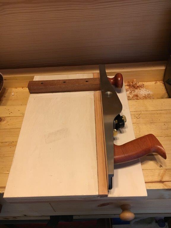
Definibile forse in italiano come tavola per intestare o intestatrice la funzione principale della shooting board è quella di rendere due fianchi consequenziali di un pezzo di legno perfettamente in squadra (quindi a 90 gradi) tra loro. E’ utile anche se vogliamo raddrizzare un fianco del legno, mettendolo in squadra con la faccia del pezzo che stiamo lavorando. E’ molto importante quindi quando vogliamo ottenere dei pezzi assolutamente squadrati, nella prospettiva della successiva esecuzione di incastri come ad esempio le code di rondine o negli incastri dente canale o nell’incastro a tenone e mortasa. Risulta particolarmente proficua nella lavorazione di testa di piccoli pezzi di legno, essendo questa un’operazione abbastanza complessa da effettuarsi nella normale morsa del banco. E’ proprio in quest’ultima lavorazione che trova il suo principale utilizzo. Può essere eventualmente equipaggiata di una o più guide per rifinire tagli precedentemente effettuati a 45 gradi (utilizzati ad esempio per le giunzioni di cornici e dei laterali delle scatole).
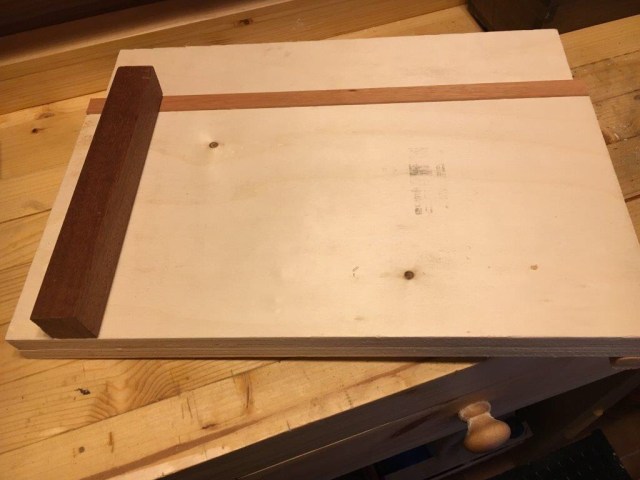
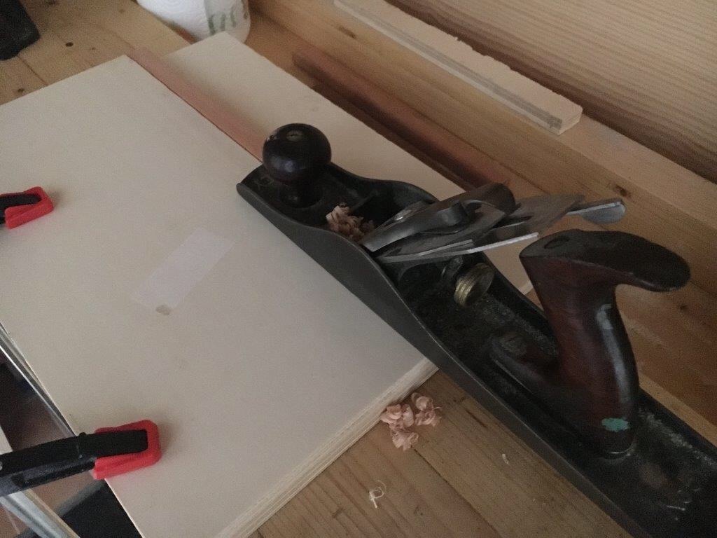
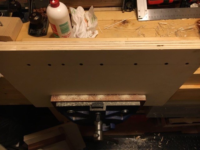
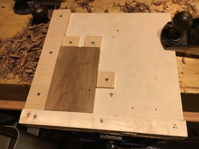
Nella sua struttura più diffusa e più semplice è costituita da due tavole di diversa misura accoppiate tra loro sulle quali viene montata (opzionale) una barra laterale di scorrimento (guida laterale) e due battute, una superiore alla quale appoggiare il pezzo che stiamo lavorando ed una inferiore che serve a bloccare la tavola stessa contro il fianco del banco o da serrarsi nella morsa. Mostro molto brevemente come ho costruito la mia shooting board.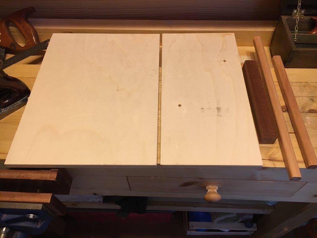 Materiale e misure: base inferiore in multistrato lunghezza 40 cm. larghezza 30 cm. spessore 1,5 cm.; base superiore in multistrato lunghezza 40 cm. larghezza 20 cm. spessore 1,5 cm.; guida laterale in legno duro lunghezza 40 cm. larghezza 2 cm. spessore 2 cm.; battuta superiore in legno duro lunghezza 22 cm. larghezza 3 cm. spessore 3 cm.; battuta inferiore in legno duro lunghezza 30 cm. larghezza 2 cm. spessore 2 cm.
Il materiale per le basi può anche essere MDF ma comunque è meglio evitare il legno massello perchè più soggetto a deformazione. La guida laterale può anche non essere inserita ma è meglio prevederla e spiegherò tra poco il perchè. La battuta superiore ed inferiore è meglio sia in legno duro, perchè più resistente agli urti ed alle scheggiature.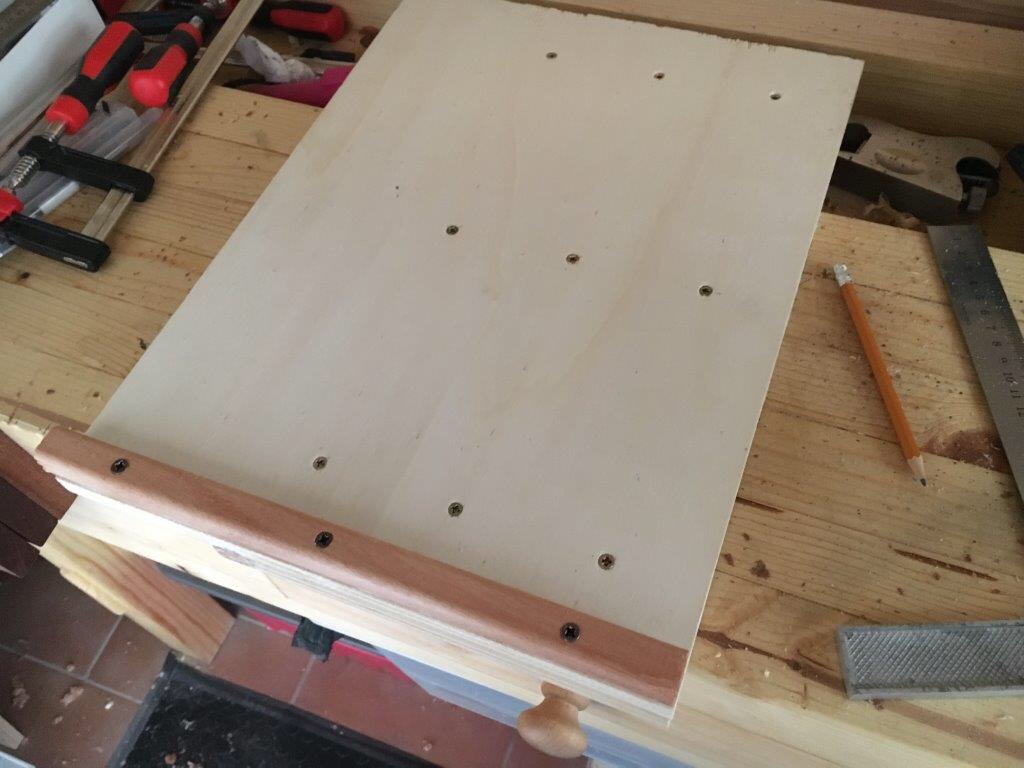 Come prima cosa ho incollato ed avvitato le due basi assieme. Le basi possono essere di misure diverse dal quelle da me utilizzate e che sono abbastanza convenzionali. L’importante è che siano di larghezza diversa così da lasciare lo spazio per ospitare l’ingombro in altezza della pialla posta in posizione reclinata. Nel mio caso ho lasciato 8 cm. (perchè 2 cm. sono sottratti dallo spessore del listello che fa da guida laterale all’azione della pialla). Si può optare anche nel solo incollare assieme le due tavole o nel solo avvitarle. Le base superiore (quella dove va incollata la guida laterale) deve avere il fianco assolutamente a 90 gradi con il piano.
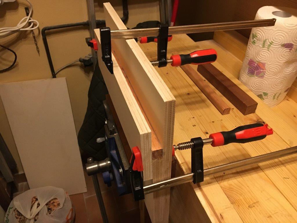
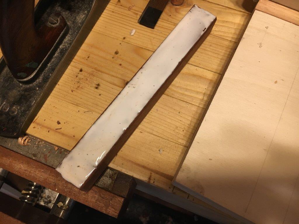
 Successivamente ho provveduto ad incollare lungo la base superiore la guida in legno duro ed piallarla perfettamente in squadra con il piano ed a livello con la base superiore. La guida è importante in quanto nella stessa viene creato lo scalino (o battuta) che permette il funzionamento della shooting board (vedremo tra breve come lavora nello specifico).
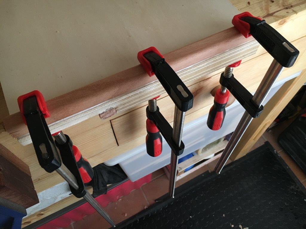
 Di seguito ho incollato ed avvitato un listello di legno duro (che può essere anche di legno dolce e di misure diverse da quelle che ho utilizzato io) che farà da battuta inferiore e permetterà il bloccaggio o serraggio della tavola. Alla battuta inferiore si può incollare una striscia di carta abrasiva così da evitarne il più possibile lo slittamento, specialmente se si prevede di utilizzarla non inserita nella morsa ma appoggiata in riscontro al fianco del banco.
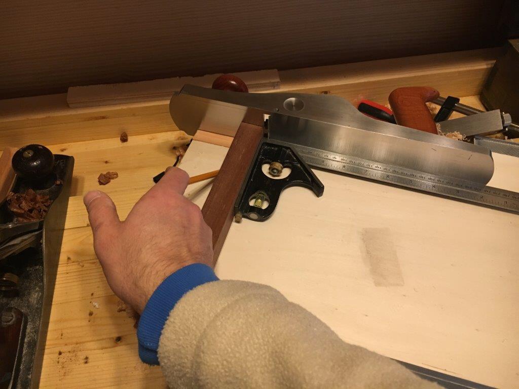
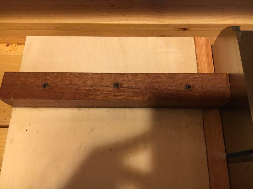
 Come ultima operazione ho provveduto ad inserire la battuta superiore in legno duro (e qui consiglio vivamente il legno duro perchè più resistente agli urti ed alle scheggiature). Ho posizionato la battuta a circa 10 cm. dal bordo della base perchè così facendo l’azione della pialla è sostenuta anche dopo aver oltrepassato la battuta stessa. La lunghezza della battuta superiore è dettata dalla larghezza della base superiore più la larghezza della guida laterale, quindi deve essere montata in modo tale che termini perfettamente a filo della guida laterale. L’inserimento della battuta superiore è uno dei punti cruciali per il corretto funzionamento della shooting board. La battuta deve essere montata assolutamente in squadra, quindi a 90 gradi, rispetto alla base della pialla posta in posizione reclinata ed a contatto della guida laterale. E’ un passaggio fondamentale perchè, se la battuta non fosse posizionata perfettamente in squadra, la shooting board sarebbe settata male in partenza ed i nostri pezzi sarebbero successivamente piallati sempre fuori squadra, vanificando di fatto il nostro lavoro.
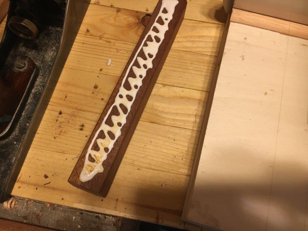
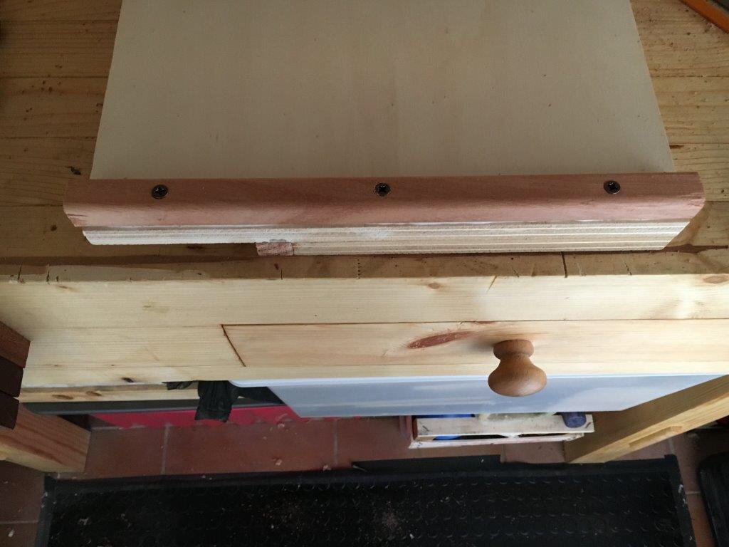
 Si può decidere di incollare direttamente la battuta al piano della shooting board, oppure soltanto avvitarla o incollarla ed avvitarla, eventualmente inserendola preventivamente in un canale scavato nella base della shooting board. Risulta particolarmente utile prevedere,al posto delle viti e della colla, l’inserimento di perni in fori praticati leggermente più larghi dei perni stessi. Questo permette di poter effettuare dei micro aggiustamenti della battuta stessa, dovesse eventualmente muoversi dalla sede e perdere la posizione in squadra con la base della pialla.
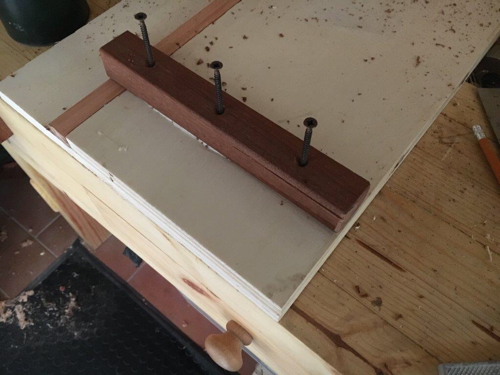
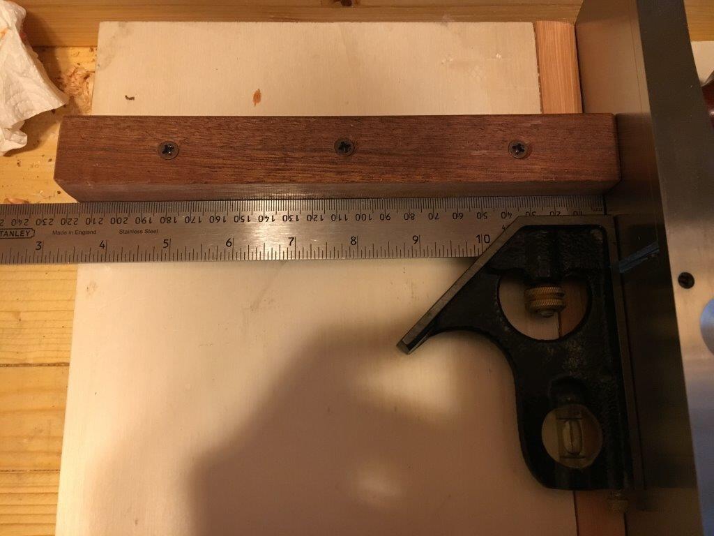 Nel mio caso ho preferito semplicemente incollare ed avvitare e fortunatamente la battuta, a distanza di tempo e dopo svariati utilizzi, non ha perso la sua posizione. Dovessi comunque costruirne un’altra in futuro opterei per la possibilità di poterla aggiustare con micro spostamenti. Questo ovvierebbe anche un eventuale errore in fase di inserimento iniziale della battuta stessa. In ogni caso se eventualmente dovesse presentarsi il problema del fuori squadro si può provvedere ad incollare un piccolo spessore in carta abrasiva che vada a compensare lo spostamento che si è creato. Infine la battuta deve avere il fianco che entra in contatto con il pezzo da lavorare in squadra con il piano della shooting board.
 In testa alla battuta sul lato più lontano ho creato uno smusso che previene eventuali scheggiature in uscita della battuta stessa durante l’utilizzo della pialla.
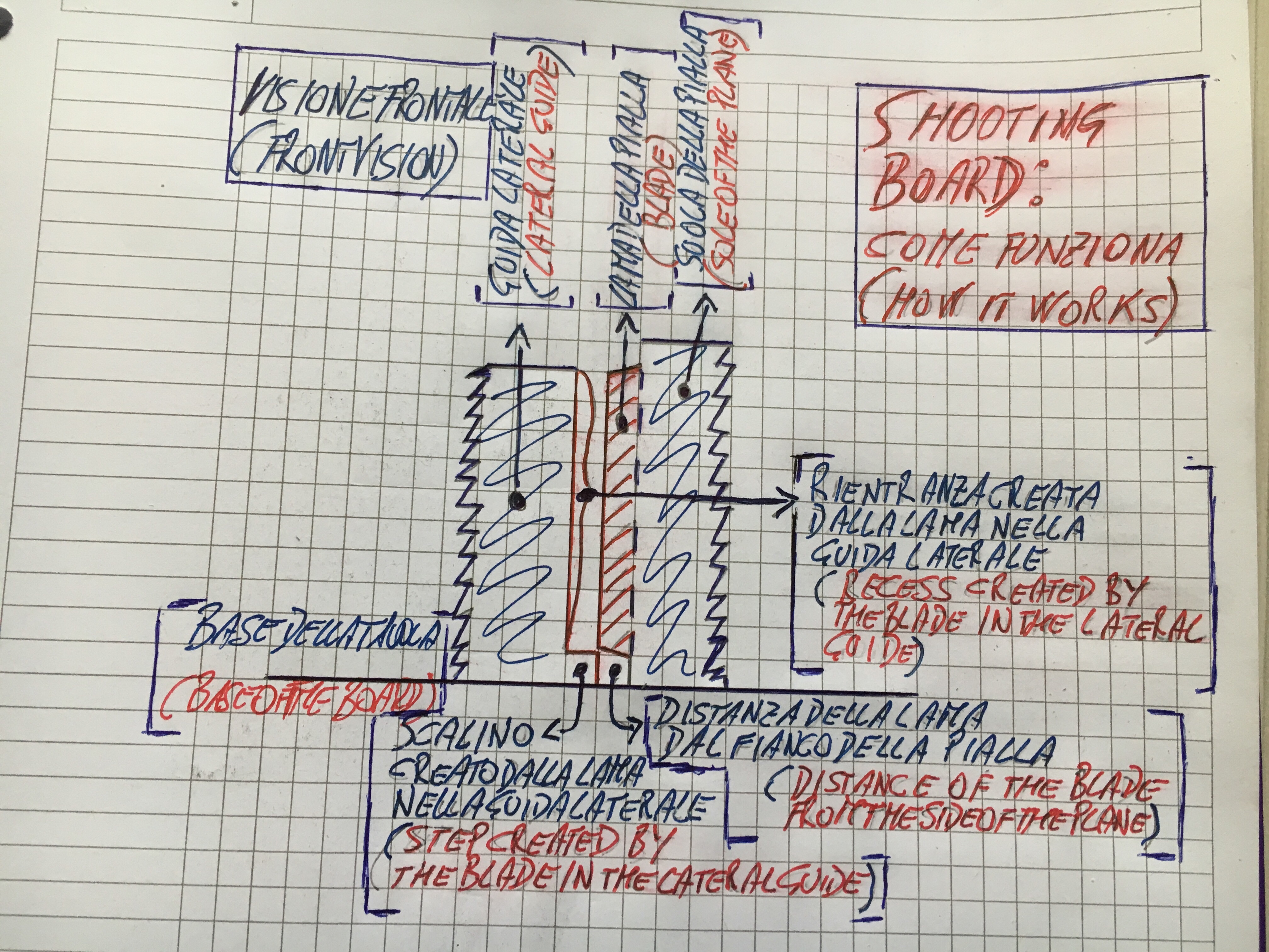
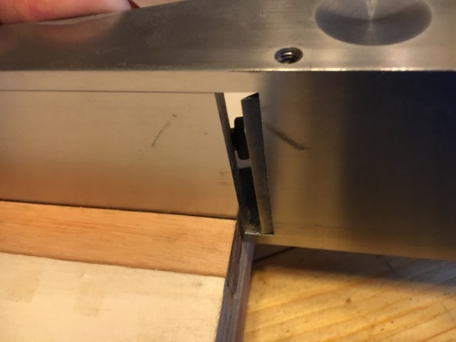
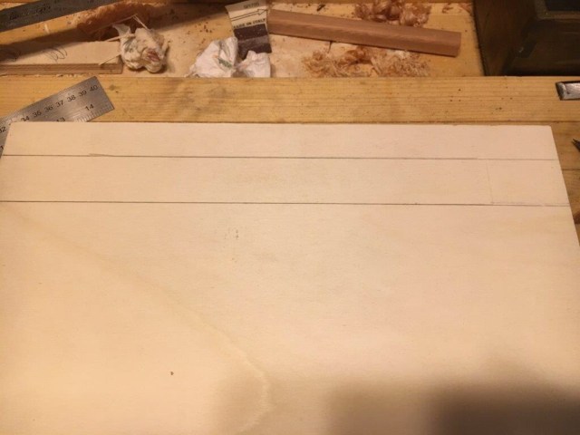
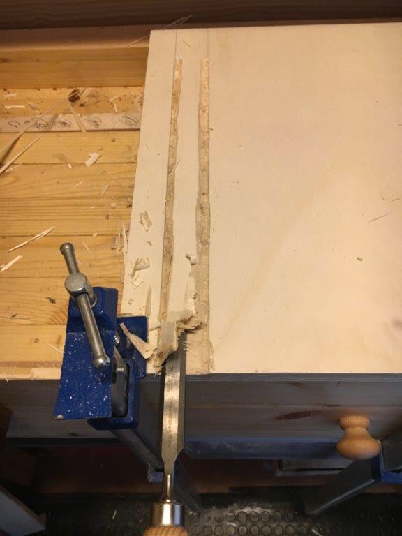
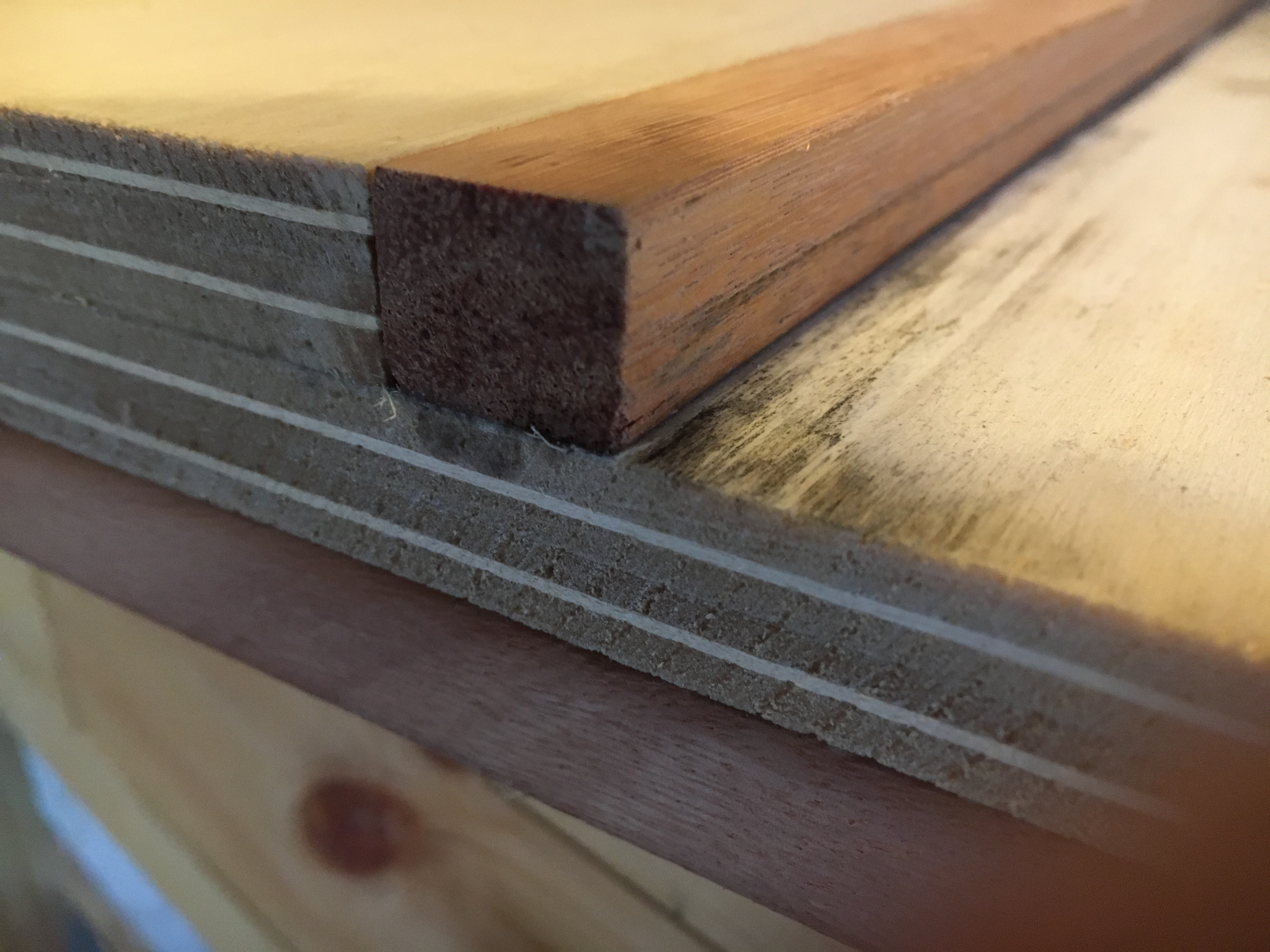 Prima di cominciare ad utilizzare la shooting board è fondamentale creare una battuta (o scalino) nella guida laterale. E’ questo l’altro elemento cruciale della shooting board, quello che permette alla stessa di poter funzionare. Infatti la domanda che tutti si fanno è: cosa evita alla pialla di mangiare tutta la guida laterale prima di arrivare al pezzo e quindi piallare all’infinito? La risposta è nella conformazione della suola della pialla stessa. Se osserviamo la suola di una pialla noteremo che la bocca della lama non corre per tutta la larghezza della base (come accade ad esempio nelle shoulder plane), ma lascia due spazi laterali, due spazi dove la lama non arriva. Quando poniamo la pialla in posizione reclinata con la base aderente alla guida laterale, facciamo poche passate con la lama che fuoriesce leggermente dalla bocca. Questo creerà un piccolo scalino nella guida, una rientranza creata dal fatto che la lama piallando la guida asporterà solo la parte superiore della guida, creando uno scavo e di conseguenza un dente, (o scalino o battuta) nella parte inferiore, uno scalino corrispondente allo spazio tra la bocca della suola ed il fianco della suola stessa. Questa piccola scanalatura che avremo creato nella guida laterale eviterà nelle azioni successive che la lama “mangi” ulteriormente la guida laterale ma pialli solo il pezzo di legno che offriamo all’azione della lama stessa.
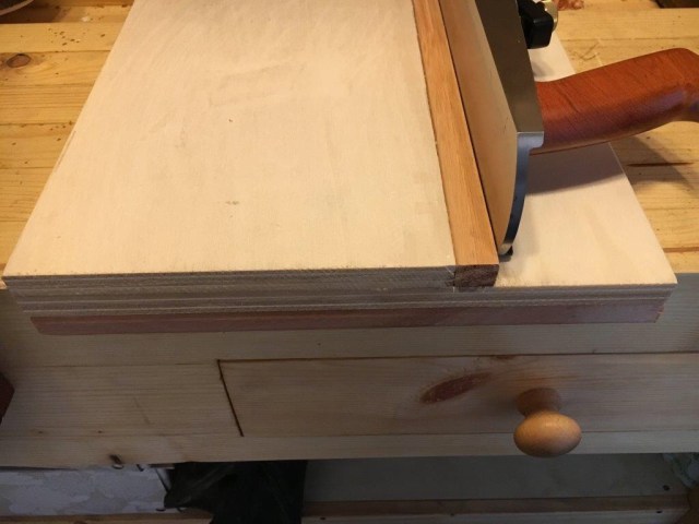
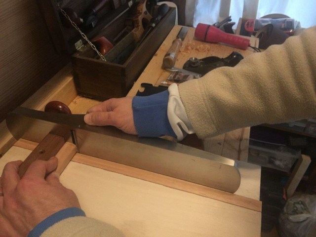
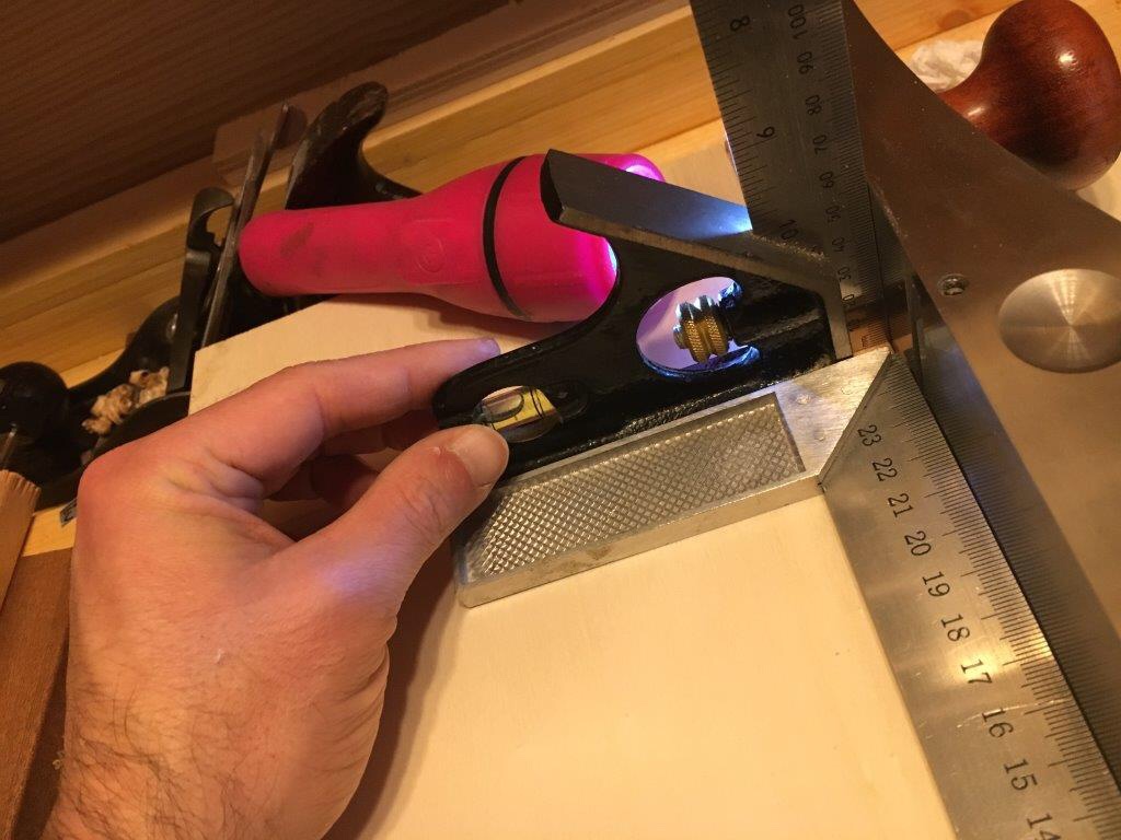
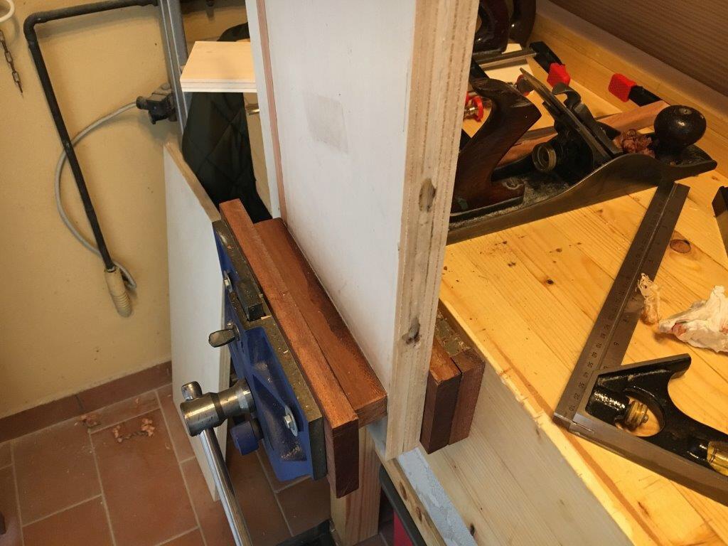
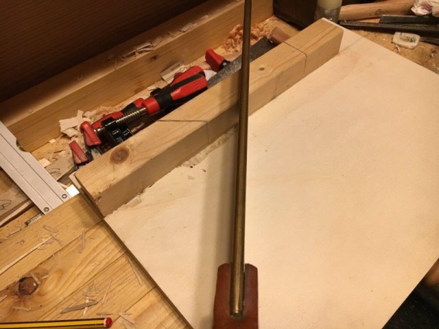
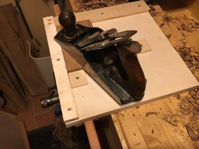
Questa sorta di “messa in strada” andrà effettuata sempre come prima cosa quando costruiamo una shooting board e successivamente ogni qualvolta dovremo smontare la lama per riaffilarla. Questo perchè ogni volta che smontiamo la lama per riaffilarla o regoliamo il settaggio di profondità della lama questa perderà l’impostazione originaria con la quale abbiamo creato lo scalino nella guida laterale. Perchè la pialla possa tornare a piallare sulla shooting board bisognerà stabilire una nuova micro battuta nella guida laterale. E questa è la principale ragione per la quale è meglio prevedere una guida laterale, una guida che, una volta usurata nel suo spessore, sia possibile sostituire semplicemente piallando il fianco della base superiore e procedendo ad incollarne una nuova. Il consiglio è quello di trovare fin da subito il giusto settaggio in profondità della lama (meglio sempre una minima protrusione della lama che asporti poco materiale per volta) e cercare di mantenerlo sempre nella stessa posizione.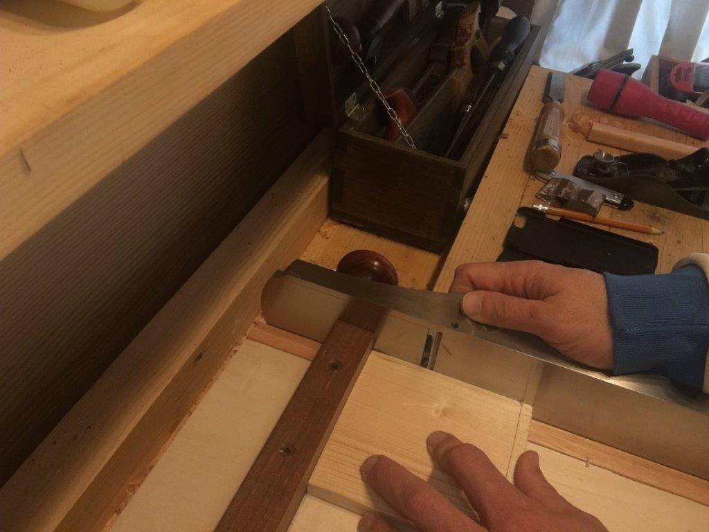 Come funziona infine la shooting board? Si serra la battuta inferiore nella morsa del banco o la si appoggia al fianco del banco stesso a riscontro. Quindi si appoggia il pezzo da piallare contro la battuta superiore facendolo sporgere minimamente e ponendolo a contrasto della base della pialla posta in posizione reclinata. La mano sinistra tiene il pezzo fermo contro la battuta e contemporaneamente spinge il pezzo verso la suola della pialla fino al contatto. La mano destra conduce la pialla in un movimento verso il pezzo ed avendo cura di mantenerla ben adesa alla base della shooting board e contro la guida laterale, in un movimento del tipo “affetta salumi”. La pratica poi ci aiuterà ad affinare la tecnica. Come detto, la shooting board è solitamente implementata con dei supporti che permettono di piallare pezzi precedentemente segati a 45 gradi. E’ possibile quindi inserire direttamente nella base un sostegno inclinato a 45 gradi oppure aiutarci con una squadra di grandi dimensioni in plastica appoggiata sulla battuta (cosa che sto facendo io).
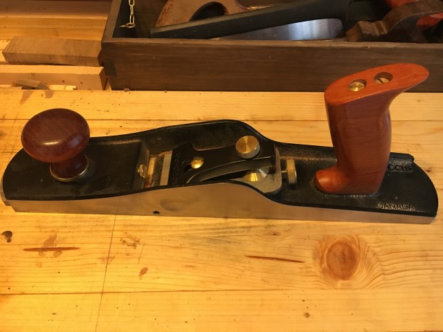
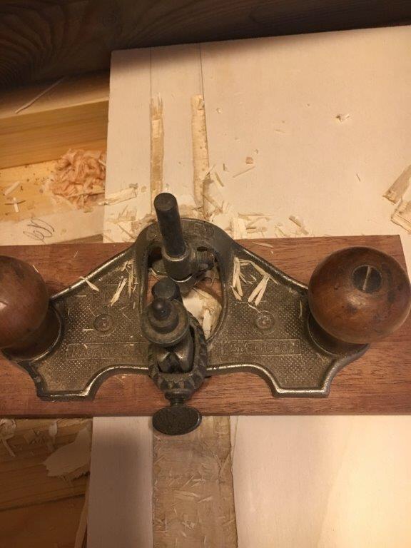
Quale pialla utilizzare? Non esiste una pialla dedicata da utilizzare. Diciamo che dovrebbe comunque possedere una certa massa ed una certa lunghezza. Quindi escludendo le shoulder plane a tutta lama nella base e le block plane, troppo piccole e leggere, diciamo che tutte le pialle dalla numero 4 fino alla 7 ed anche oltre vanno bene. Io utilizzo la Veritas low angle, bevel down, n. 5 jack plane e devo dire che mi ci trovo benissimo. E’ dotata di una buona massa e lunghezza ideale, la presentazione della lama in versione bevel down aiuta molto per la piallatura del legno di testa ed è provvista di una scanalatura nel fianco laterale che ne suggerisce e facilita l’utilizzo proprio sulle shooting board in posizione reclinata. Trovate sotto dei link dove poterla acquistare.
https://www.axminster.co.uk/veritas-low-angle-jack-planes-ax932288
Il prezzo non è propriamente accessibile, ma è un ottimo prodotto che durerà una vita. Detto questo nulla vieta comunque di utilizzare le classiche pialle bevel down. Funzionano egregiamente e se proprio vogliamo utilizzarle consiglio comunque la numero 5 o la numero 7.
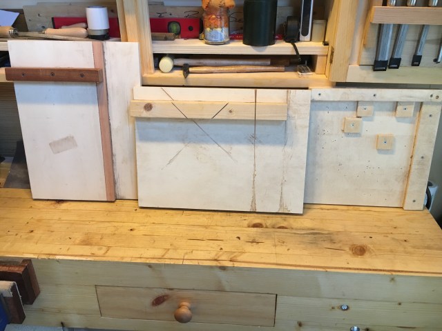
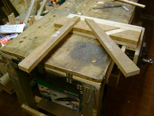
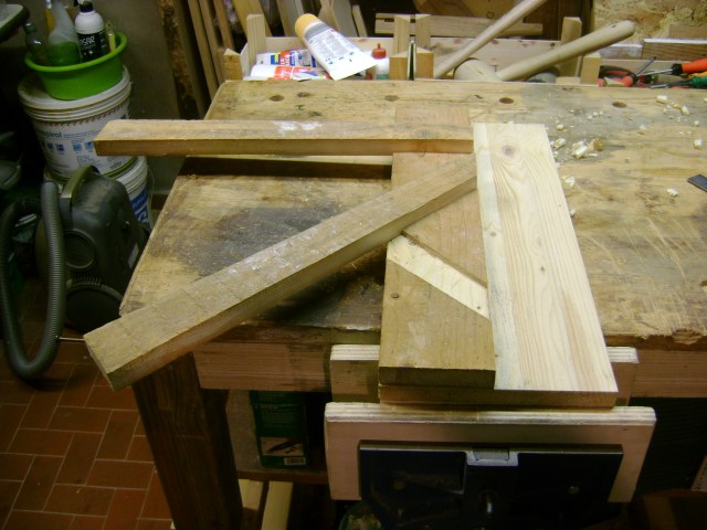
E’ possibile realizzare shooting board personalizzate. Quella da me proposta e realizzata è una versione per così dire “moderna”. Se vogliamo un qualcosa di più classico possiamo orientarci sulla costruzione di un modello sul tipo di quello raffigurato sopra, che ho realizzato qualche anno fa e che funziona ugualmente bene.
Bench hook (mitre board)
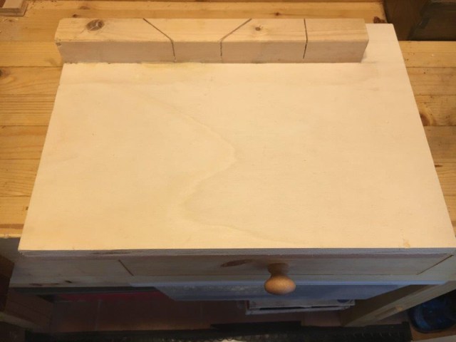
Il bench hook (in italiano potremmo definirla tavola per segare) è un supporto sul quale poter segare agevolmente pezzi di ridotte dimensioni. Possono essere costruiti in coppia così da permettere una maggiore stabilità del pezzo, specialmente se questo è di lunghe dimensioni. Come per la shooting board, il bench hook può essere realizzato in svariate forme e grandezze e prevedere alcuni optional che ne aumentano la versatilità di utilizzo. Nella sua versione base si presenta come una tavola sulla quale sono inserite due battute. Una inferiore che serve da stop ed una superiore che può prevedere la possibilità di effettuare tagli anche a 45 gradi. Di seguito riporto come ho realizzato la mia tavola.
Materiale e misure: base in multistrato lunghezza 42 cm. larghezza 30 cm. spessore 2 cm.; battuta superiore in legno di pino, lunghezza 36 cm. larghezza 4 cm. spessore 4 cm.; battuta inferiore in legno duro lunghezza 42 cm. larghezza 2 cm. spessore 2 cm. La realizzazione è molto semplice.
Sulla base in multistrato (si può utilizzare anche MDF e meglio comunque del legno massello per ragioni di indeformabilità) ho praticato uno scavo di qualche millimetro di profondità ed a circa 3 cm. dal bordo nel quale ho inserito la battuta, che poi ho incollato ed avvitato in più punti. Si può tranquillamente non prevedere lo scavo e procedere ad incollare o soltanto avvitare alla base (nel mio caso le viti sono poste sotto alla base della tavola). Per una maggiore stabilità ho comunque preferito unire le due cose. La battuta è in legno di pino (ma è preferibile usare un legno duro) e volutamente più corta della base per permettere di segare anche esternamente ed in appoggio alla battuta.
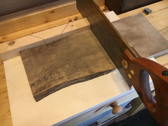
Nella battuta ho successivamente praticato con la tenon saw due tagli in opposte direzioni ed a 45 gradi per effettuare i tagli obliqui ed un taglio perpendicolare per i tagli dritti. È preferibile praticare i tagli guida con la stessa sega che si pensa di utilizzare normalmente in seguito. Non è fondamentale che i tagli guida siano assolutamente precisi perché andranno comunque rifiniti successivamente sulla shooting board. I tagli guida devono essere praticati fino alla base della tavola. Essendo il listello incollato ed avvitato sotto la base i pezzi della battuta sezionata non si sposteranno dalla loro sede una volta segati. Per finire ho incollato ed avvitato sotto la base un listello di legno duro che fa da battuta per l’inserimento nella morsa del banco o a riscontro del fianco del banco aggiungendo eventualmente una striscia di carta abrasiva per aumentare l’aderenza.
Il funzionamento è molto semplice. Si blocca nella morsa la battuta inferiore e si pone il pezzo da tagliare a riscontro della battuta superiore. Si inserisce la sega nella sede di taglio desiderato e si procede a segare. Durante l’azione cerchiamo di mantenere ben saldo ed aderente il pezzo alla battuta e di segare il più dritto possibile, mantenendosi ovviamente sempre all’interno del taglio guida. Nel tempo è normale che la base si usuri in corrispondenza dei tagli guida e venga a poco a poco tagliata. Ciò non compromette comunque in alcun modo la funzionalità della tavola ma per questo motivo è buona regola prevedere uno spessore abbondante del piano della tavola.
Planing board
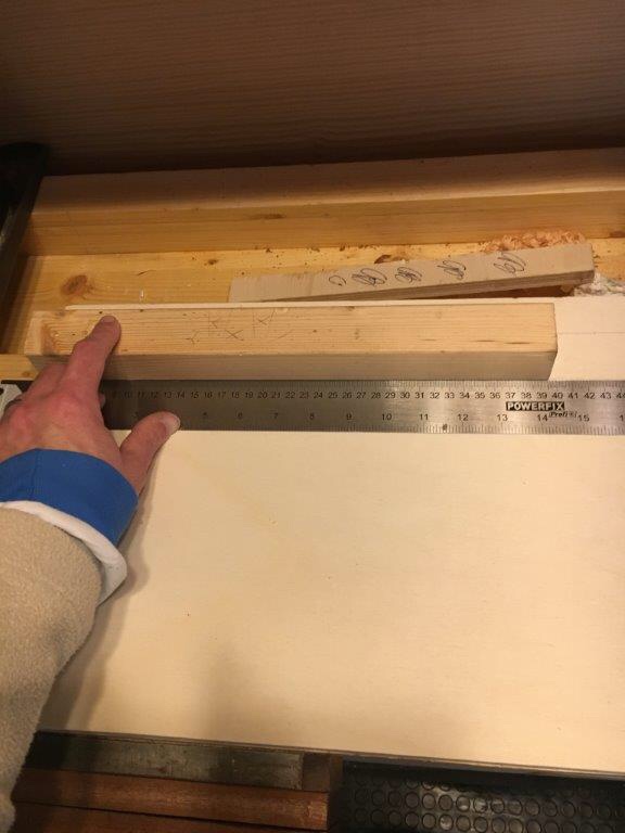
La planing board (in italiano potremmo definirla tavola per piallatura) serve a piallare più agevolmente la superficie di piccoli pezzi di legno e portarli allo spessore desiderato. Così come per le altre tavole viste sopra la planing board può essere realizzata in svariati modelli e dimensioni. Nel mio caso volevo dotarmi di un qualcosa che si attagliasse particolarmente alle mie necessita di dover piallare le facce di tanti piccoli pezzi di svariate misure. Quindi nel mio caso non era di fondamentale importanza l’ottenere una superficie assolutamente piana, quanto il dotarmi di una tavola la più versatile possibile. Dopo aver cercato e visto molti modelli in rete penso di essermi dotato di una planing board mai vista prima, quasi una mia invenzione, almeno che io sappia. Illustro di seguito il materiale utilizzato e come è stata realizzata.
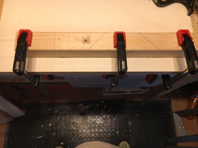
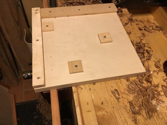
Base in multistrato lunghezza 30 cm. larghezza 30 cm. spessore 2 cm.; battuta laterale bassa lunghezza 27,5 cm. larghezza 4,5 cm. spessore 0,5 cm.; battuta laterale alta lunghezza 30 cm. larghezza 3 cm. spessore 1 cm.; battute mobili 4 cm. per 4 cm. per 0,5 cm. di spessore; battuta inferiore lunghezza 50 cm. per 2 cm. per 2 cm. Le battute laterali sono avvitate su due fianchi della base e sono di diversa altezza così da permettere un appoggio più consono al pezzo che si sta lavorando e permettere inoltre un miglior riscontro visivo mentre si pialla. Le battute mobili sono in multistrato così come le battute laterali e sono preforate al centro per permettere l’inserimento della vite senza che si spacchino visto l’esiguo spessore.
Il funzionamento è semplice. Si appoggia il pezzo da lavorare in battuta al riscontro laterale e si piazzano una o più battute mobili a ridosso del pezzo, avvitandoli alla base. In questo modo avremo sempre il pezzo bloccato in qualsiasi posizione desideriamo. L’unico limite sarà nella grandezza della tavola stessa. Anche in questo caso la tavola è ampiamente personalizzabile. Possiamo usare multistrato o MDF per tutti i componenti della tavola ed anche il legno massello, specialmente per le battute mobili, che possiamo creare anche di altra forma. L’importante è non esagerare nell’altezza delle battute laterali e dei blocchetti o risulterà impossibile piallare il pezzo vicino ai bordi.
_____________________________________________________________
It is difficult to correctly define these woodworking devices in italian. In English they are called generically jig and, although literally the translation in Italian is maschera, I think that it is more suitable to refer to them as ausilio. In practice, however, even in Italy they are known by their English name and so it is better to refer to them as jigs without complicating life too much. What are these boards and what is useful? Briefly, they are very useful when you have to work small pieces, when you are currently working in little space and precision finishing is required. Said so is very reductive and generic and does not do justice to the importance that these boards have in certain processes. So let’s see what they do, how they are built and how they work.
Shooting board
Perhaps we can name it in Italian as intestatrice or tavola per intestare. The main function of the shooting board is trimming a piece of wood and squaring the end grain so to make two consecutive sides of a piece of wood perfectly in square (at 90 degrees). It is also useful if we want to straighten a side of the wood, putting it in square with the face of the piece we are working on. It is very important therefore when we want to obtain absolutely squared pieces, in the perspective of the subsequent execution of joints such as dovetails or dado joints or mortise and tenon joint. It is particularly useful when we are squaring the edges of small pieces of wood, especially end grain, as this operation is quite difficult to be made in the bench vise. And it is in this last processing that its main use is found. It may optionally be equipped with one or more guides to finish cuts previously made at 45 degrees (used for example for the frames and side edges of the boxes).In its most widespread and simpler structure it is made up of two differently sized coupled boards on which an optional lateral guide and two bars, one up, the fence, where we put the piece we are working, and one down that serves to lock the board against the side of the bench or to be clamped in the vice. I show very briefly how I built my shooting board. Material and measures: lower base in plywood length 40 cm. width 30 cm. 1.5 cm thick; upper base in plywood length 40 cm. width 20 cm. 1.5 cm thick; lateral guide in hard wood length 40 cm. width 2 cm. 2 cm thick; top fence in hardwood length 22 cm. width 3 cm. 3 cm thick; lower wooden stop length 30 cm. width 2 cm. thickness 2 cm.The material for the boards can also be MDF but anyway it is better to avoid solid wood because it is more subject to deformation. The side guide may not be inserted but it is better to predict it and I will explain in a moment why. The fence and lower stop is better both in hard wood, because it is more resistant to shocks and splitting. First I glued and screwed the two bases together. The bases can be of different sizes from those used by me and that are quite conventional. The important thing is that they are of different width so as to leave space to accommodate the height of the plane placed in reclined position. In my case I left 8 cm. (because 2 cm are subtracted from the thickness of the lateral guide to). You can also choose only to glue up together the two boards or just screwing them together. The upper base (the one where the lateral guide is to be glued) must have the side absolutely at 90 degrees with the plane.Subsequently I proceeded to glue the hard wood guide along the upper base and plane it perfectly in square with the top and level with the upper base. The guide is important because in it I created the ledge or lip that allows the operation of the shooting board (we’ll see soon how it works in the specific).Below I glued and screwed a hardwood piece (which can also be of soft wood and of different sizes from those I used) that will serve as a stop and will allow the locking or tightening of the board. At the lower stop you can glue a strip of abrasive paper so as to avoid slippage as much as possible, especially if you plan to use it not inserted in the vice but resting in the counter side of the bench.As a last operation, I proceeded to insert the upper fence (and here I highly recommend the hardwood because it is more resistant to shocks and splitting). I placed the fence about 10 cm. from the edge of the base because doing so the action of the plane is well supported even after passing the fence itself. The length of the upper fence is dictated by the width of the upper base plus the width of the side guide, so it must be mounted in such a way that it ends perfectly flush with the side guide. The insertion of the upper fence is one of the critical points for the correct working of the shooting board. The fence must be assembled absolutely in square, therefore at 90 degrees, with respect to the base of the plane placed in reclined position and in contact with the lateral guide. It is a fundamental step because, if the fence was not positioned perfectly in square, the shooting board would be set badly at the start and our pieces would then be planed always out of square, effectively nullifying our work.You can decide to directly glue up the fence to the shooting board, or just screw it or glue it and screw it, eventually inserting it in a rabbet created in the base of the shooting board. It is particularly useful to insert, instead of screws and glue, pins into holes made slightly wider than the pins themselves. This allows you to make micro adjustments to the fence itself, if it move from the seat and lose the square position with the sole of the plane.In my case I preferred to simply glue and screw and fortunately the fence, after some time and after several uses, has not lost its position. Should I still make another in the future I would opt for the possibility of being able to adjust with micro movements. This would also obviate any error in the initial insertion of the fence itself. In any case, if the out-of-square problem should arise, you can glue a small piece of abrasive paper to compensate for the movement that has been created. Further, the fence must have the side that comes into contact with the piece to be worked in the square with the shooting board base.At the head of the fence on the farthest side I created a bevel that prevents any splitting of the fence itself during the use of the plane.Before starting to use the shooting board it is important to create a lip (or ledge) in the side guide. This is the other crucial element of the shooting board, the one that allows it to work. In fact, the question that everyone makes is: what prevents the plane to plane all the side guide before you get to the piece and then plane it endlessly? The answer is in the shape of the sole of the plane itself. If we look at the sole of a plane we will notice that the blade’s mouth does not run all the way across the base (as in the shoulder plane, for example), but leaves two lateral spaces, two spaces where the blade does not reach. When we place the plane in a reclined position with the base adhering to the lateral guide, we make a few passes with the blade that comes out slightly from the mouth. This will create a small step or lip or ledge in the guide, a recess created by the fact that the blade planing the guide will remove only the upper part of the guide, creating a groove and consequently a tooth, (or step) in the lower part, a step corresponding to the space between the mouth of the sole and the side of the sole itself. This small groove that we have created in the lateral guide will avoid in subsequent actions that the blade “further” eats the lateral guide but only planes the piece of wood that we offer to the action of the blade itself. This sort of “putting in the street” will always be done first when we build a shooting board and then every time we have to disassemble the blade to re-sharpen it. This is because every time we disassemble the blade to re-sharpen it or adjust the depth setting of the blade this will lose the original setting with which we created the step in the lateral guide. If we want the plane to go back to planing on the shooting board it will be necessary to establish a new micro ledge in the lateral guide. And this is the main reason why it is better to provide a lateral guide, a guide that, once worn in its thickness, can be replaced simply by planing the side of the upper base and proceeding to glue a new one. The advice is to immediately find the right setting in depth of the blade (better always a minimum protrusion of the blade that take away little material at each pass) and try to keep it in the same position.How does the shooting board work? Tighten the lower stop in the bench vice or put it against the side of the bench. Then place the piece of wood to be trimmed against the fence making it protrude minimally and placing it in contrast to the sole of the plane placed in reclined position. The left hand holds the piece firmly against the fence and at the same time pushes the piece towards the sole of the plane until contact. The right hand leads the plane in a movement towards the piece and taking care to keep it well anchored at the base of the shooting board and against the lateral guide, in a movement of the “sliced cured meat” type. The practice will then help us to refine the technique. As said the shooting board is usually implemented with supports that allow you to plane pieces previously sawn at 45 degrees. It is therefore possible to insert a 45 degree inclined support directly into the base or to help us with a large plastic square resting on the fence (which I am doing).Which plane to use? There is not a dedicated plane to use. Let’s say that it should possess a certain mass and a certain length. So excluding the full width blade shoulder planes and the block planes, too small and light, all the planes from number 4 up to 7 and even beyond are fine. I use the Veritas low angle, bevel down, n. 5 jack plane and I must say that I’m fine with it. It is with a good mass and ideal length, the presentation of the blade in the bevel down position helps a lot for the planing of the end grain and is provided with a groove in the side that suggests and facilitates its use on the shooting board in reclined position. Find below the links where you can buy it. https://www.axminster.co.uk/veritas-low-angle-jack-planes-ax932288. The orine is not properly accessible, but it is a great product that will last a lifetime. That said, however, nothing wrong about using the classic bevel down planes. They work very well and if you really want to use them I still recommend the number 5 or number 7.It is possible to create personalized shooting boards. The one I have proposed and created is a so-called “modern” version. If we want something more classic we can orient ourselves on the construction of a model on the type of the one shown above, which I realized a few years ago and that works equally well.
Bench hook (mitre board)
The bench hook (in Italian we could name it tavola per segare) is a support on which to easily cut pieces of small dimensions. They can be built in pairs so as to allow greater stability of the piece, especially if this is of long dimensions. As for the shooting board, the bench hook can be made in various shapes and sizes and provide some options that increase the versatility of use. In its basic version it looks like a board on which two fences are inserted. A lower batten that serves as a stop and a top fence that can provide the ability to make cuts even at 45 degrees. Below I report how I made my board.Material and measures: plywood base, length 42 cm. width 30 cm. 2 cm thick; top fence in pine wood, length 36 cm. width 4 cm. 4 cm thick; lower batten in hard wood, length 42 cm. width 2 cm. 2 cm thick. The realization is very simple.In the base in plywood (you can also use MDF, always better than solid wood for reasons of non-deformability) I made a groove a few millimeters deep and about 3 cm. from the edge where I inserted the fence, which I then glued and screwed in several places. You can proceed just with the glue up or just with only screwing the base (in my case the screws are placed under the base of the board). For greater stability I still preferred to combine the two things. The fence is made of pine (but it is preferable to use hardwood) and deliberately shorter than the base to allow sawing also externally and in support of the fence .In the fence, I then practiced with the tenon saw two cuts in opposite directions and 45 degrees to make oblique cuts and a perpendicular cut for straight cuts. It is preferable to make the guide cuts with the same saw that you plan to use normally later. It is not essential that the guide cuts are absolutely precise because they will still be finished later on the shooting board. The guide cuts must be made up to the base of the board. As the fence is glued and screwed under the base, the sections of the cut-out stop will not move from their seat once sawn. Finally I glued and screwed under the base a strip of hardwood that acts as a stop for putting in the bench vice or against the side of the bench eventually adding a strip of abrasive paper to increase the grip. Working is very simple. The lower stop is clamped in the vice and the piece to be cut is placed in correspondence with the upper fence. Insert the saw into the desired cutting site and proceed with sawing. During the action we try to keep the piece firmly and adhering to the fence and to cut as straight as possible, always keeping inside the cutting guide. Over time it is normal for the base to be worn near the guide cuts and gradually cut. However, this does not compromise the functionality of the board in any way but, for this reason, it is good practice to provide an abundant thickness of the board.
Planing board
The planing board (in Italian we could call it tavola per piallatura) is used to more easily plane the surface of small pieces of wood and to bring them to the desired thickness. As for the other boards seen above the planing board can be made in various models and sizes. In my case, I wanted to equip mine with something that would be particularly suited to my need of having to plane the faces of many small pieces of various sizes. So in my case it was not of fundamental importance to obtain an absolutely flat surface, as to give me a board as versatile as possible. After looking and seeing many models on the net I think I made a planing board never seen before, almost my invention, at least that I know. I show below the material used and how I made it. Plywood base, length 30 cm. width 30 cm. 2 cm thick; lower fence length 27.5 cm. width 4.5 cm. 0.5 cm thick; higher fence length 30 cm. width 3 cm. 1 cm thick; moving stops 4 cm. for 4 cm. for 0.5 cm. thick; lower batten length 50 cm. for 2 cm. for 2 cm. The side fences are screwed on two sides of the base and are of different height so as to allow a more appropriate support to the piece that you are working on and also allow a better visual feedback while you plane it. The moving stops are in plywood as well as the fences and are pre-drilled in the center to allow the insertion of the screw without splitting because of its low thickness. Working is simple. The piece to be worked is placed against the lateral fence and one or more moving stops are placed close to the piece, screwing them to the base. In this way we will always have the piece locked in any position we want. The only limit will be the size of the board itself. As the other boards also in this case the board is widely customizable. We can use plywood or MDF for all the components of the board and also solid wood, especially for moving stops, which we can also create in other shapes. The important thing is not to exaggerate the height of the lateral fences and the moving stops or it will be impossible to plane the piece near the edges.

Lascia un commento