Pialle particolari. Pialle per scanalature: l’incorsatoio / Special planes. Grooving planes: the plough (plow) plane
English translation at the end of the article Nel variegato panorama delle pialle ne esistono alcune che definirei particolari perché si discostano molto sia dalla tipica forma della pialla che nel tipo di lavorazione che effettuano. Tra queste abbiamo già parlato della router plane , un particolare tipo di pialla utile per determinate lavorazioni nel legno come ad esempio il livellare il fondo di un incastro. In questo post vorrei parlare di un’altra tipologia di pialla: l’incorsatoio. Ci si riferisce spesso erroneamente a questo utensile
come ad una pialla combinata multifunzione o, come riportavano alcuni cataloghi d’epoca, addirittura come ad una pialla universale, in grado di effettuare qualsiasi lavorazione. La Stanley 55 ne fu un esempio. In realtà solo con alcuni modelli di incorsatoio particolarmente complessi è effettivamente possibile fare molte lavorazioni che comunque, all’atto pratico, sono spesso risultate poco efficaci e di difficile settaggio oltre a non essere particolarmente performanti.
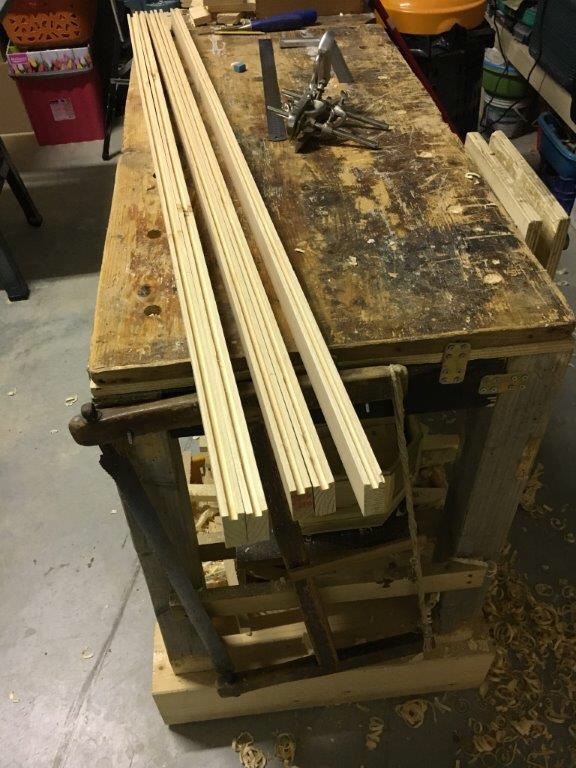
Riferendoci quindi alle versioni più semplici di incorsatoio (quelli più specifici per talune lavorazioni), questi possono effettuare essenzialmente due tipi di lavorazione: scanalature lungo la venatura del legno (e talvolta traverso vena) e battute nel legno.
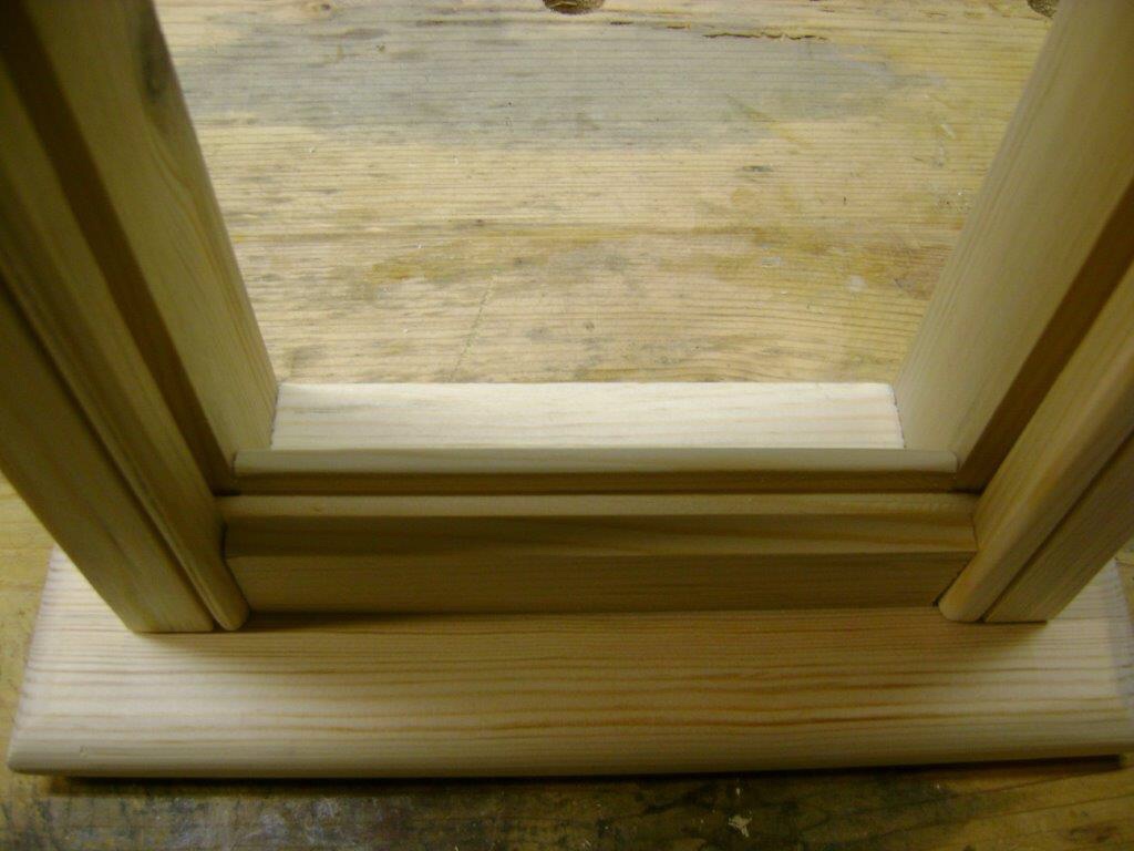
Nella falegnameria amanuense questa pialla è in grado di creare canali nei quali è possibile inserire dei pannelli o dei vetri (basti pensare alla realizzazione delle pannellature di ante, sportelli, finestre e porte, retro di mobili), o dei fondi dei cassetti, o praticare delle perlinature (utilizzando le apposite lame utili a formare l’incastro dente e canale) e per svariati altri utilizzi dove si debba comunque ricavare una scanalatura in grado di ospitare qualcosa.

In passato era un utensile molto diffuso ma oggi alcuni elettroutensili (come la sega da banco e la fresatrice elettrica) lo hanno di fatto sostituito svolgendo lo stesso lavoro con maggior speditezza. Trovo però che questo attrezzo abbia ancora una sua valenza nella falegnameria per l’efficacia e la precisione di lavorazione.
A prima vista la sua conformazione può intimidire un po’. Il suo utilizzo non è molto intuitivo e necessita di tempo per essere settato a dovere e prima di poterlo far lavorare. Ma una volta compreso il suo funzionamento ci si rende subito conto di quale piccolo capolavoro di ingegneria si tratti. Ancora oggi i pochi moderni produttori di questo attrezzo costruiscono l’incorsatoio ricalcando il modello originale, con pochissime varianti, a testimonianza della bontà della sua realizzazione. Gli storici costruttori di questo tipo di pialla hanno cessato di costruirlo ormai da decenni ma, come detto, alcune case produttrici moderne, come ad esempio la Veritas, propongono degli esemplari di ottima fattura anche se a prezzi non propriamente a buon mercato.
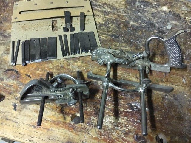
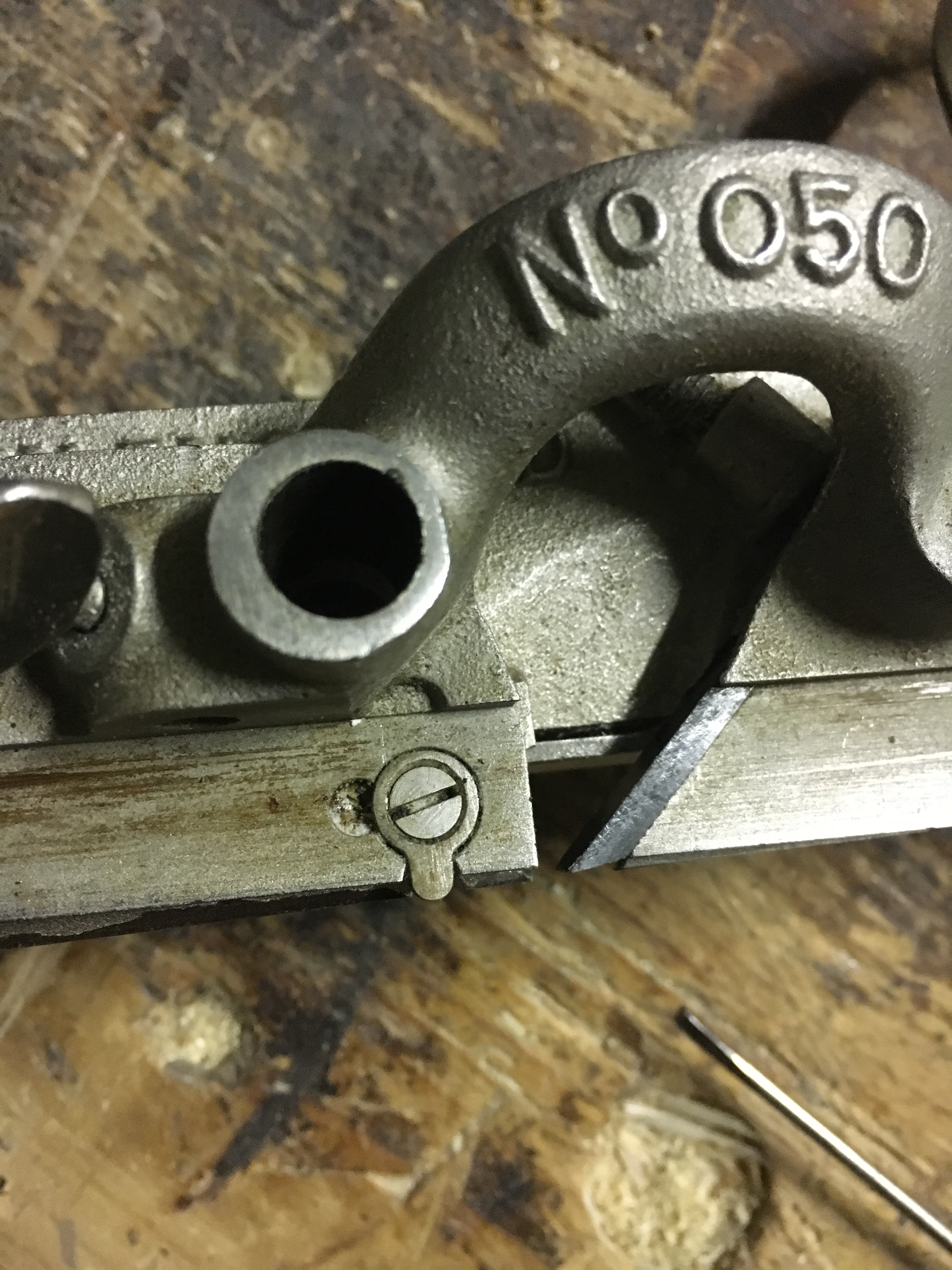
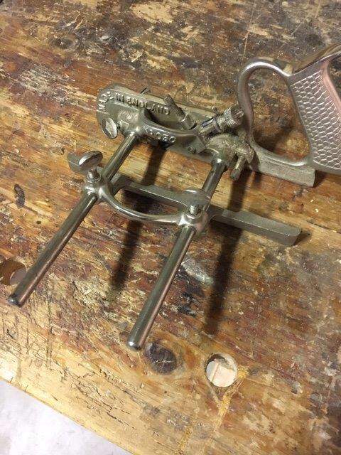
I marchi storici sono, come sempre in questo campo, Record e Stanley. Questi due produttori hanno fabbricato in passato molte tipologie di incorsatoio ma quattro modelli su tutti sono divenuti molto comuni. Si tratta dei Record (e Stanley) 043 e 044 e, tra gli incorsatoi cosiddetti combinati, lo Stanley 45 e il Record 050. Questo tra le tipologie in metallo. I primissimi modelli di incorsatoio furono però costruiti in legno e tra i più famosi marchi possiamo annoverare Marples, Mathieson, e Sandusky, tanto per citarne alcuni. L’acquisto di un usato dovrebbe quindi indirizzarsi verso i suddetti noti produttori.
L’incorsatoio opera generalmente lungo le fibre del legno, quindi lungovena, creando delle scanalature dritte e parallele al pezzo che stiamo lavorando. Alcuni particolari tipi di incorsatoio possono però lavorare anche traverso vena. In realtà, come vedremo in seguito, anche taluni comuni incorsatoi possono lavorare traverso vena purché dotati di spurs, piccoli taglienti in grado di recidere le fibre traverso vena e permettere la lavorazione anche su questo tipo di venatura.
Incorsatoi in legno
I primi incorsatoi erano fatti in legno, con alcuni inserti in ottone, acciaio ed altri materiali. La storia ci ha consegnato anche taluni esemplari costruiti in materiali molto costosi costruiti guardando più all’estetica che non alla reale loro efficienza. Le dimensioni sono molto generose e di peso non indifferente, spesso superiore alle sorelle in metallo.
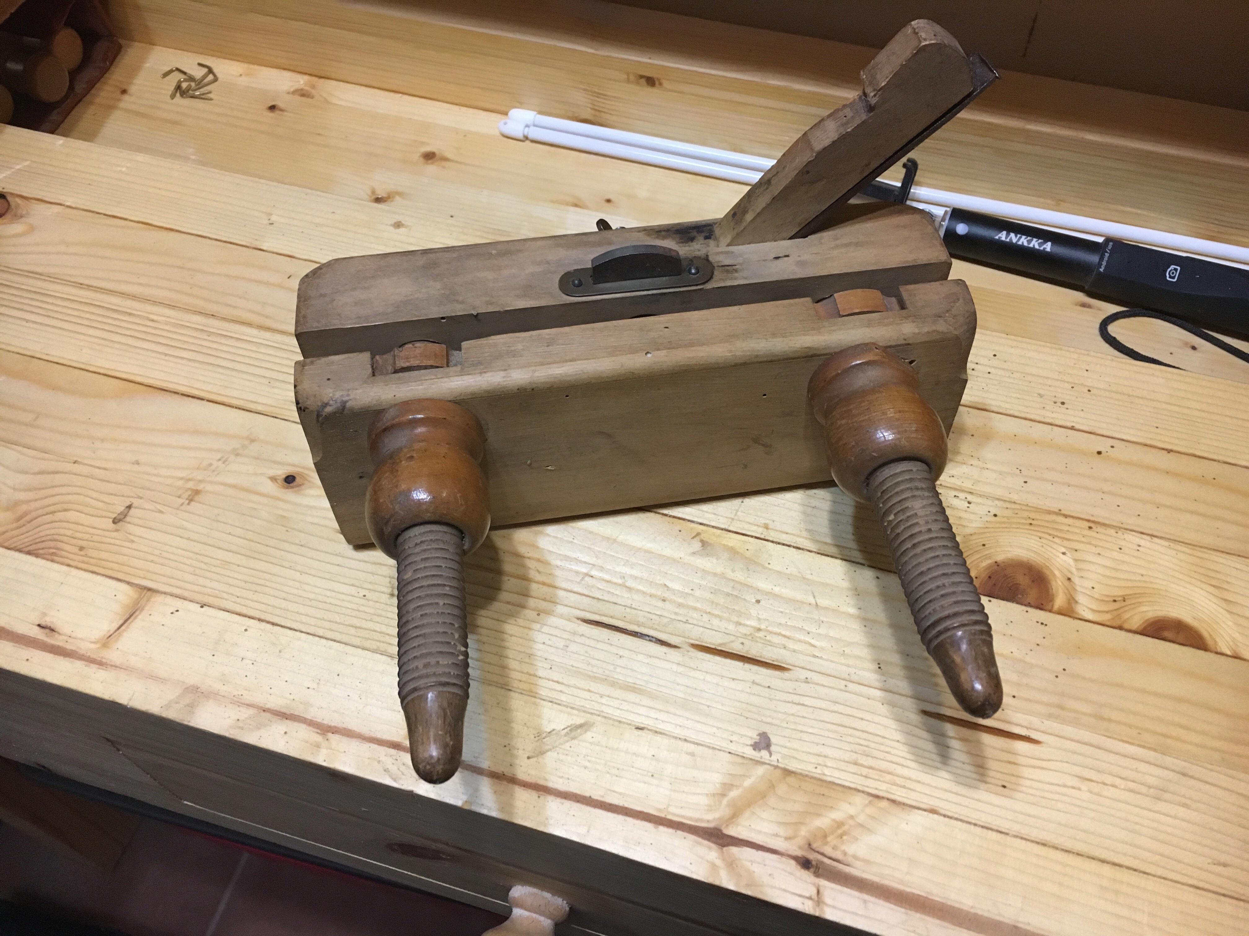
La conformazione ed il loro funzionamento però sono del tutto simili alle più moderne pialle in metallo. Nonostante il peso e le dimensioni non proprio contenute il loro utilizzo è sempre molto piacevole (come per tutte le pialle in legno) e questo è dovuto essenzialmente alla facilità di scivolamento del legno sul legno. I modelli più antichi prevedevano il bloccaggio della guida parallela mediante dei cunei. Il sistema funzionava bene ma le forti sollecitazioni a cui erano soggetti i cunei facevano sì che talvolta questi potessero sganciarsi dalla guida. Si è cercato di ovviare al problema creando una guida che prevedesse un sistema di settaggio e blocco sempre in legno ed incentrato su un meccanismo di pomelli scorrevoli su di una filettatura creata nel legno stesso. In questi modelli la stabilità e la precisione risultano maggiori.

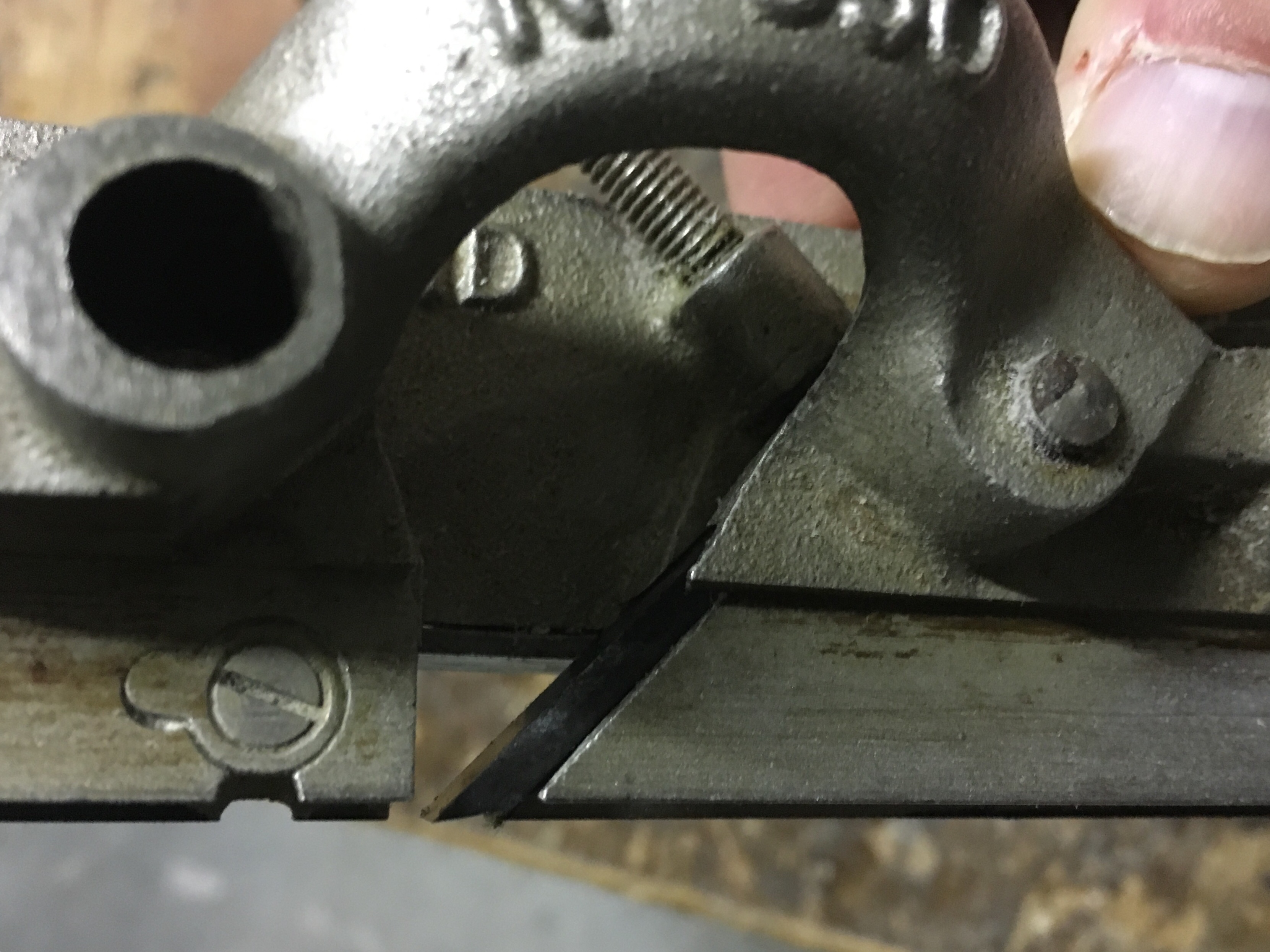
Come per tutte le pialle in legno la lama viene inserita nella bocca scavata nel corpo pialla e tenuta ferma in posizione mediante un cuneo. Molti modelli sono dotati di stop di profondità e di un tagliente per recidere la fibre traverso vena. La conformazione della lama si presenta più spessa alla base e rastremata in alto. Questo per dare una pendenza che contrasti la spinta in fase di piallatura prevenendo il movimento della lama tra la bocca ed il cuneo. La particolarità di alcune lame è inoltre la presenza di una scanalatura sul dorso della lama in posizione centrale che ne permetteva l’alloggiamento. L’utilizzo di questo tipo di pialle richiede una certa forza, ben compensata dalla piacevolezza durante l’impiego. Oggigiorno pochissimi produttori costruiscono incorsatoi in legno. E’ consigliabile quindi cercare nel mercato del vintage dove sono presenti molti marchi tra cui spiccano, come detto, Marples e Sandusky. Una valida alternativa, se si possiedono le competenze, è dedicarsi all’autocostruzione.
Incorsatoi in metallo
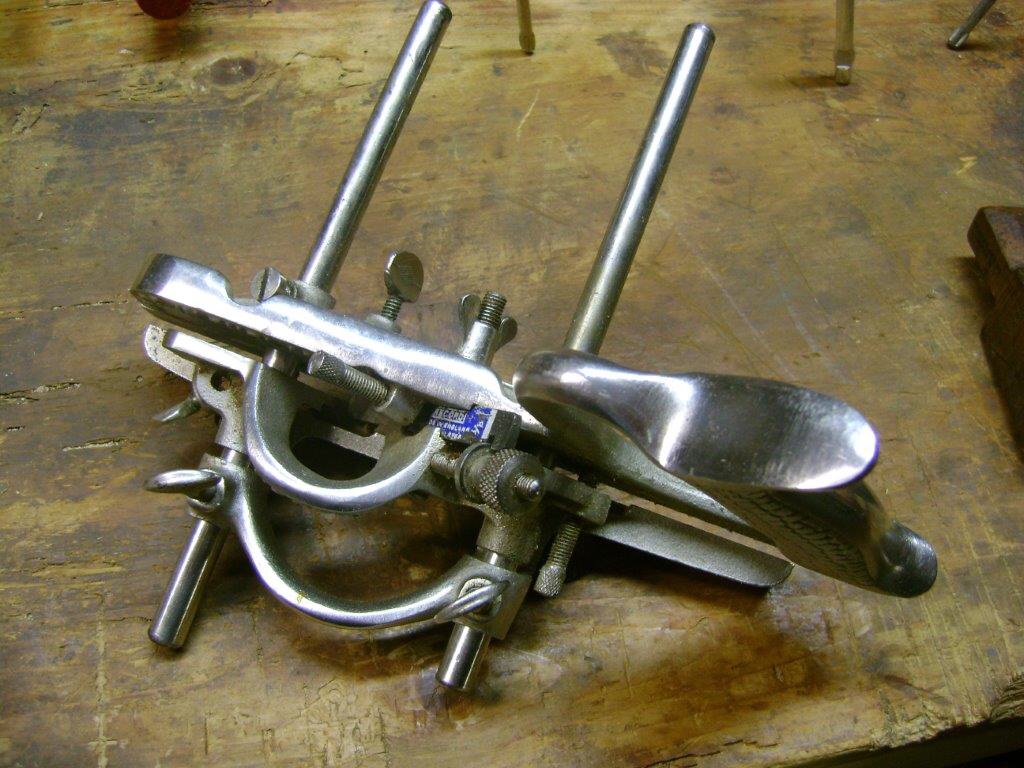
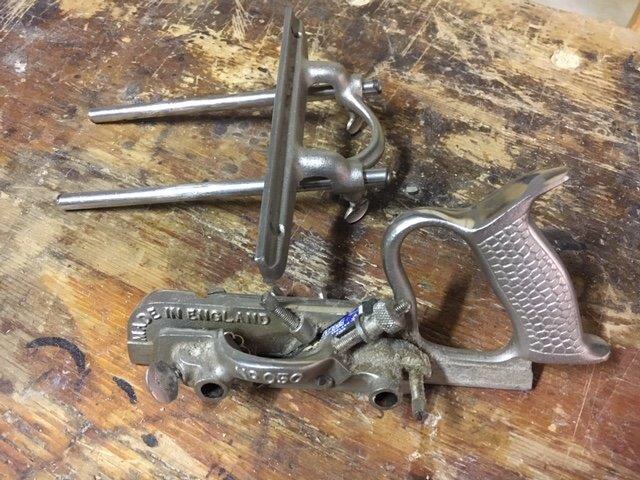
Gli incorsatoi in metallo sono quelli che conosco meglio e sui quali posso quindi spendere qualche parola in più. Possiedo infatti una Record 043 ed una Record 050. Gli incorsatoi in metallo sono ovviamente di fattura più recente rispetto a quelli in legno. I due marchi storici come detto sono Record e Stanley che hanno continuato a produrli almeno fino alla metà dello scorso secolo. A prima vista l’incorsatoio è di difficile comprensione. Brevemente si può dire che è costituito di un corpo in metallo sul quale si inserisce una lama e lateralmente un blocco lama (o slitta) ed una guida parallela che scorre su due barre che si inseriscono nel corpo pialla stesso. Completano l’utensile uno stop di profondità, due lame per incidere traverso vena ed un deflettore di trucioli. Questo molto sommariamente. Adesso vediamo nel particolare le varie parti di un incorsatoio, nello specifico un incorsatoio combinato modello Record 050, accennando poi successivamente al Record 043. Sostanzialmente i modelli Record e Stanley 043 e 044 sono molto simili, sicuramente più semplici e a dire di molti anche più efficaci degli incorsatoi combinati.
Record 050A (improved comination plane)
A) corpo principale in metallo dove è ricavata l’impugnatura (senza rivestimento nei più diffusi modelli Record) o rivestita in legno o plastica in altri modelli. Nel corpo principale è ricavata la scanalatura nella quale si inserisce la lama. In quest’ultima è presente una fessura nella quale si inserisce e agisce la rotella di regolazione di profondità della lama. È presente inoltre una sorta di battuta che andrà a formare il parallelismo con la slitta presente sul fianco della pialla.
Nel corpo pialla sono inoltre presenti vari alloggiamenti per le barre di scorrimento della guida, lo stop di profondità, il deflettore per i trucioli, e le varie viti di bloccaggio, come quella che permette la pressione verso il basso della lama.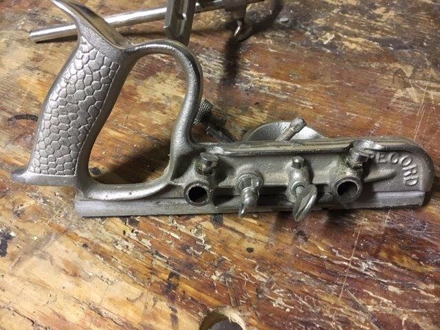
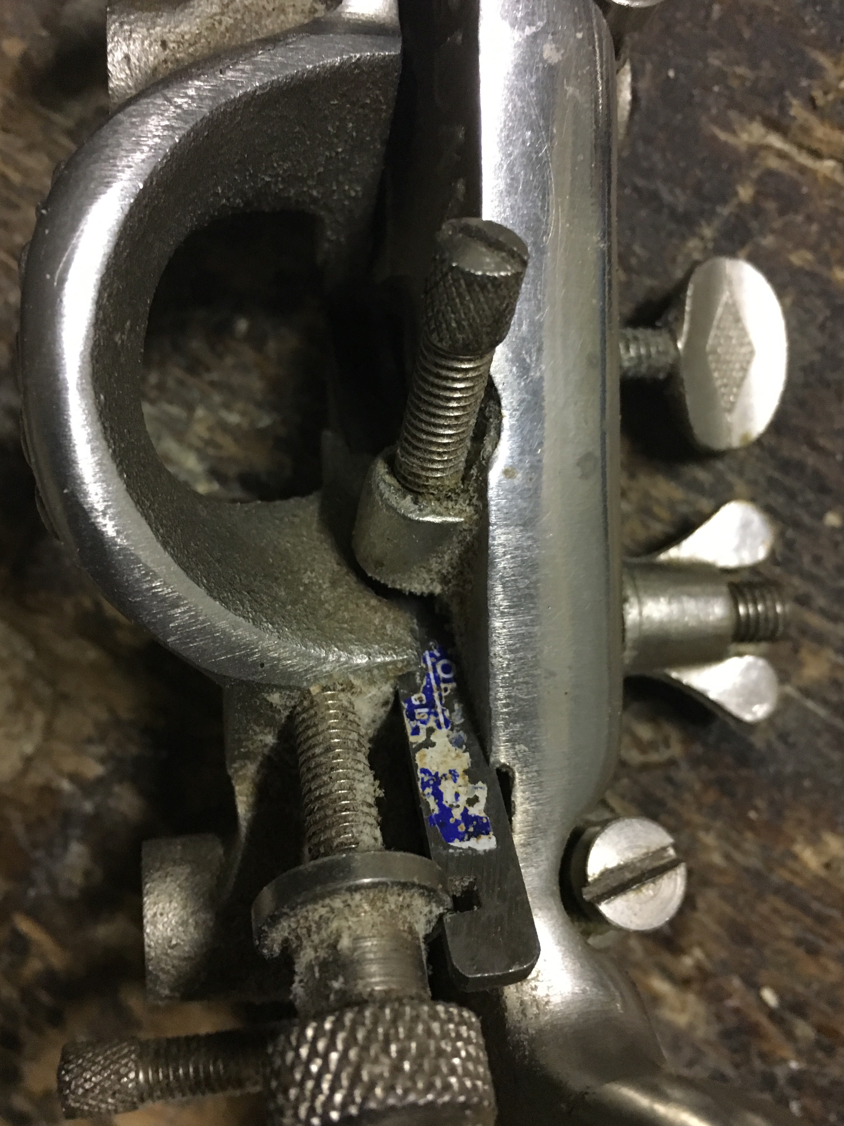
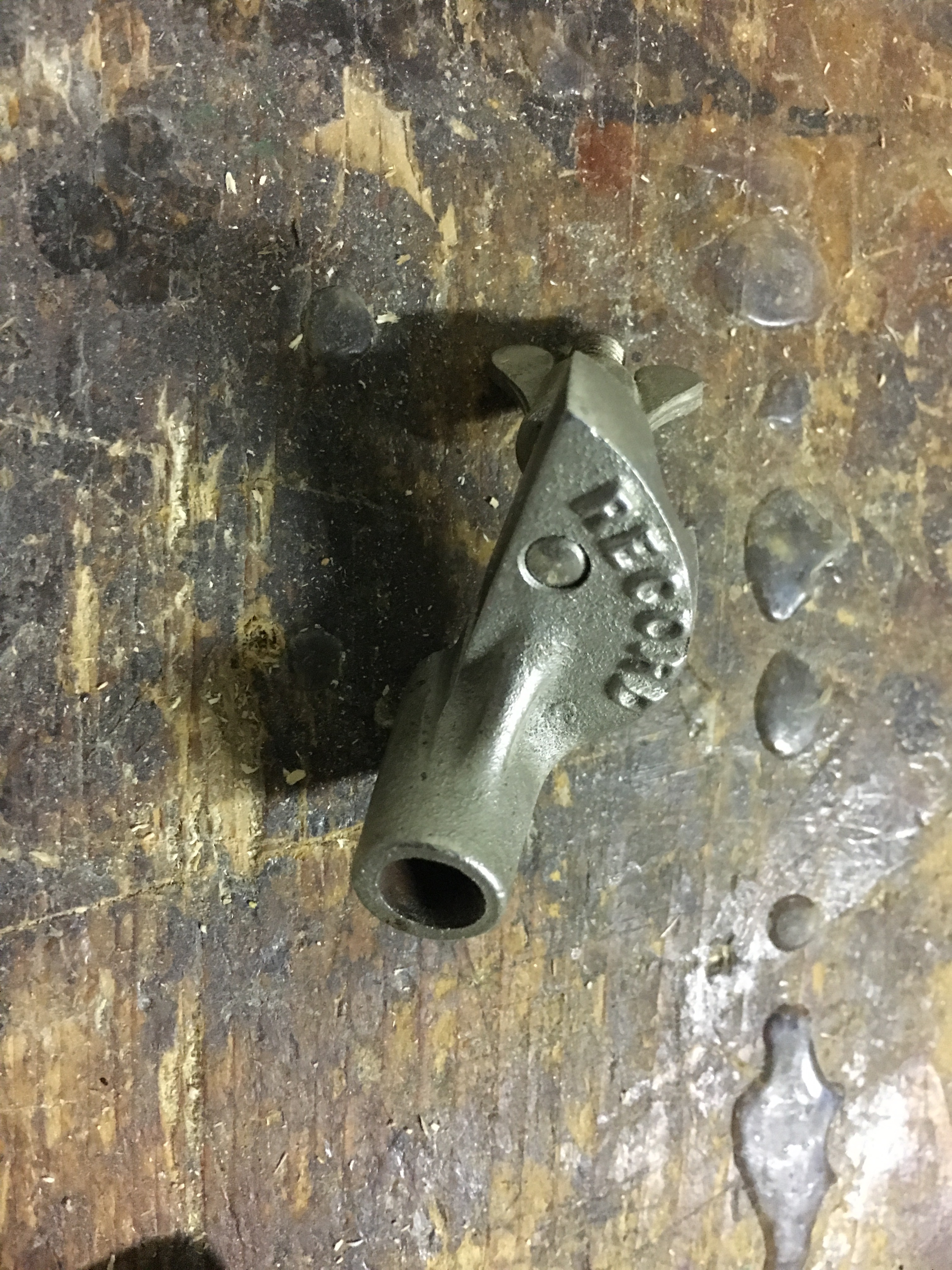
B) slitta o sezione scorrevole che si collega al corpo pialla mediante una vite a galletto. La slitta chiude lateralmente la lama contro il corpo pialla ed è provvista di impugnatura. Una vite sul retro della slitta consolida e mantiene il parallelismo della slitta con il corpo pialla.
C) Guida parallela che permette di mantenere perpendicolare e sempre alla stessa distanza l’incorsatoio rispetto al fianco del pezzo dove si sta creando la scanalatura. La guida parallela si inserisce e scorre su due barre di metallo tra loro parallele che si inseriscono a loro volta nel corpo pialla. La guida si blocca sulle barre mediante delle viti a galletto. A loro volta le barre metalliche si bloccano mediante viti.
Alla guida parallela è possibile avvitare una riscontro in legno duro così da incrementare la profondità di appoggio della guida. È buona regola, prima dell’uso, lubrificare sia la slitta dell’ incorsatoio che la basetta in legno così da facilitare l’azione di piallatura.
D) Lo stop di profondità è una basetta in metallo (rimovibile) che permette la predeterminazione della profondità della scanalatura. Scorre su un cilindro di metallo e si blocca mediante una vite a galletto. Il funzionamento è semplice. Durante l’azione di piallatura l’incorsatoio scende di profondità man mano che progredisce nella scanalatura. Quando la basetta entrerà in contatto con il pezzo in lavorazione questa non permetterà alla lama di tagliare ulteriormente.
E) Il deflettore di trucioli è un elemento rimovibile che, una volta inserito, permette l’espulsione laterale del truciolo anzichè verso l’alto.
F) Gli spurs sono due piccole rotelle dotate di un tagliente che possono essere utilizzati per recidere le fibre quando si deve lavorare traversovena. Utilizzando un cacciavite è possibile allentare la vite che le mantiene in posizione ritratta e ruotarle in modo da far fuoriuscire la piccola lama. Prima del loro utilizzo la vite va ovviamente serrata di nuovo.
G) per sostenere le due lame più strette bisogna rimuovere la slitta laterale ed inserire nella barra posteriore della guida parallela l’apposito supporto in dotazione.
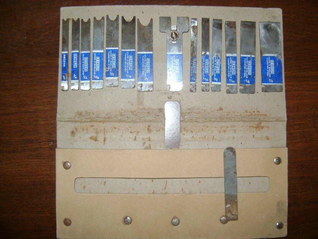
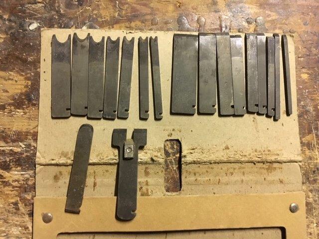
Gli incorsatoi in metallo venivano forniti con alcune lame di varie misure così da potersi adattare alla varie lavorazioni. Le misure più comuni sono: 3 mm; 4,5 mm; 6 mm; 8 mm; 9,5 mm; 12,5 mm. Le lame più comunemente usate erano quelle con forma a parallelepipedo, ma gli incorsatoi multifunzione venivano forniti di molte più lame di diverse forme e dimensioni (dente e canale, forma stondata, a corno) così da poter praticare svariate lavorazioni e molteplici modanature (la Record 050A era venduta con 17 lame).
Affilatura
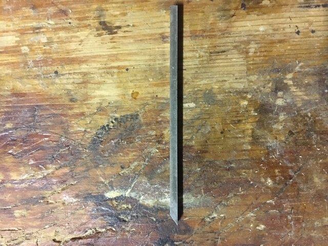
Gli incorsatoi lavorano con il tagliente della lama rivolto verso il basso. Solitamente le lame vengono affilate a 30 gradi ma si possono trovare anche affilature tra i 25 ed i 30 gradi. L’importante è non creare mai un’affilatura dove il tagliente sia più basso dell’estremità dello stesso, altrimenti sarebbe impossibile far lavorare la lama nel legno. Come detto le lame sono provviste di una scanalatura che ne permette l’inserimento della rotella di regolazione di profondità. Rispetto alle comuni lame delle pialle le lame degli incorsatoi sono molto strette e questo, se da un lato ne permette una veloce affilatura, dall’altro impone di prestare particolare attenzione affinché venga creato un tagliente dritto, specialmente se affiliamo a mano libera. Se il tagliente è storto anche il fondo della scanalatura verrà storto.
L’artigiano falegname Paul Sellers consiglia anche di smussare leggermente i fianchi delle lame (non vicino al tagliente), così da favorirne l’azione di piallatura. I vecchi modelli di lama erano già prodotti con un dorso della lama più stretto rispetto all’altro, praticamente dando alla lama una forma trapezoidale. Prima dell’affilatura del tagliente è bene verificare sempre la planarità del dorso della lama stessa prestando attenzione che sia dritto o leggermente concavo. Un’eventuale convessità andrebbe invece corretta attraverso una morsettatura dei punti più alti e con l’ausilio di una leva in contropressione. L’affilatura può essere fatta sulle pietre diamantate o con altri tipi di pietra o su carta abrasiva, rivolgendo lo smusso verso il basso e tenendo la lama con le dita pollice e medio e l’indice poggiato sul dorso. Durante l’affilatura a mano libera le dita dell’altra mano possono sorreggere il movimento consentendo maggior controllo. Si può procedere infine alla lappatura con la pasta abrasiva sullo strop come visto nel post sull’affilatura.
Funzionamento
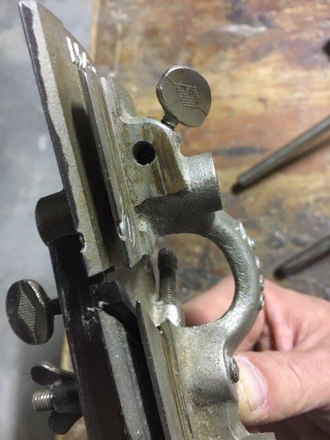
1) Allentando la vite a galletto posta sul fianco del corpo pialla si allenta la slitta laterale così da fare spazio per l’inserimento della lama.
La lama si inserisce da sotto, con il tagliente rivolto verso il basso e si inserisce nell’apposita scanalatura creata nel corpo pialla. L’incavo presente nella lama serve per l’inserimento della rotella che regola la profondità della lama. Si stringe nuovamente la vite a galletto e si serra la vite presente sopra la lama dell’ incorsatoio.

La lama deve essere ben serrata tra il corpo pialla e la slitta ma non al punto da non permettere il funzionamento della rotella di profondità. All’inizio della lavorazione la protrusione della lama deve essere minima.

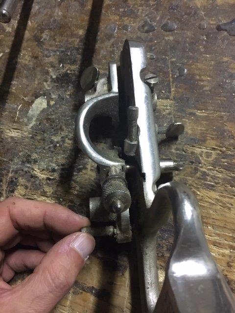
2) Si inserisce la guida parallela sul lato sinistro del corpo pialla (se destrorsi) attraverso le barre cilindriche di scorrimento. La guida e le barre si settano alla distanza voluta dal fianco del pezzo da lavorare e quindi si serrano le viti della guida e delle barre di scorrimento.
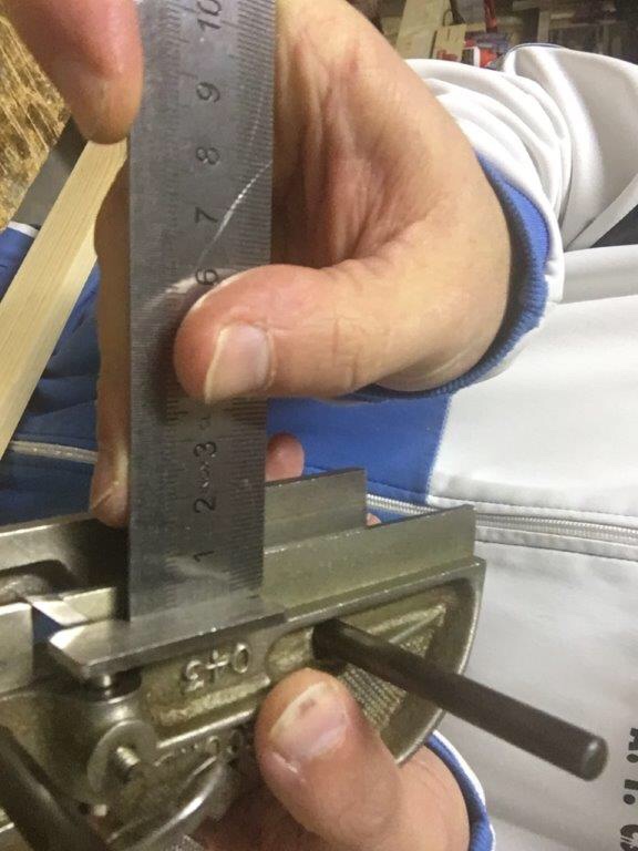
3) Si inserisce il deflettore di trucioli (opzionale) e lo stop di profondità negli appositi alloggiamenti e si serrano mediante le viti a galletto. Lo stop di profondità si regola con l’ausilio di un righello o altro strumento di misurazione. Lo stop di profondità funziona come detto sopra.
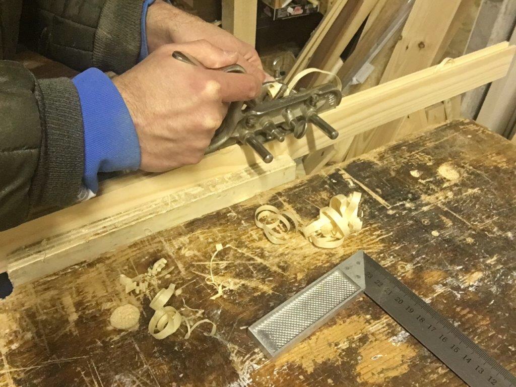
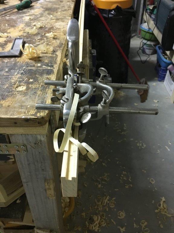
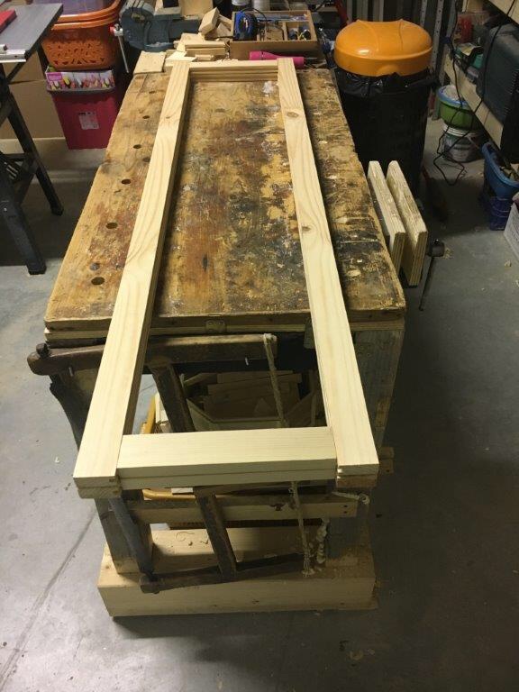
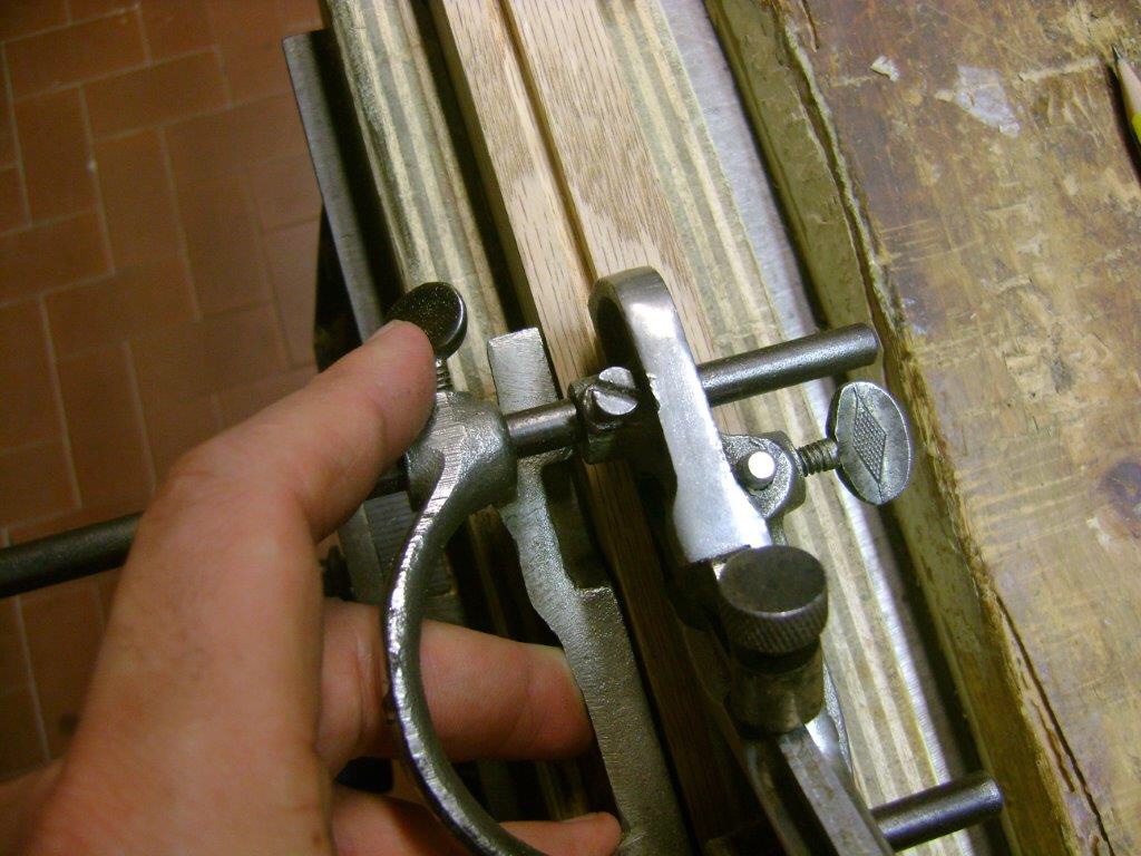
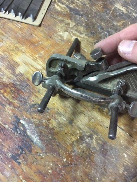
4) Mantenendo l’utensile perpendicolare al pezzo di legno da lavorare la mano destra spingerà in avanti l’attrezzo e l’altra mano sorreggerà la guida mantenendola ben adesa al pezzo da lavorare. Il lavoro più importante lo svolge sicuramente la mano che sorregge la guida. Il movimento di spinta non deve essere troppo forzato in quanto la lama, se affilata a dovere, farà tutto il lavoro.
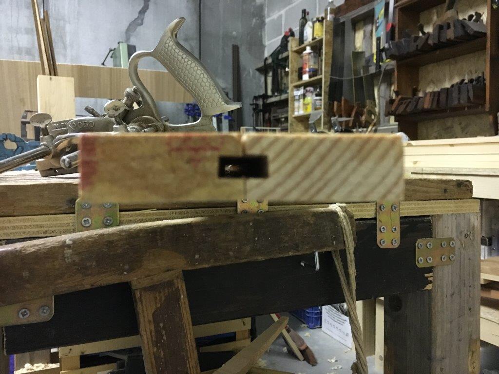
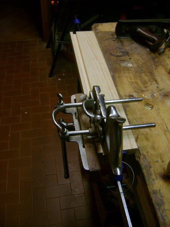
<img class=”size-full wp-image-3068″ src=”https://crearobi.blog/wp-content/uploads/2018/11/img_4355.jpg” width=”576″ height=”768″ /
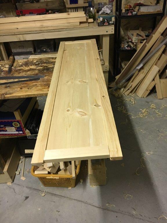
Si inizia dal punto più lontano davanti a noi a circa 10 cm. dall’estremità del pezzo da lavorare e, con una breve e leggera passata, si stabilisce un primo solco nel legno. Se siamo soddisfatti della posizione del solco si procede con movimenti a ritroso sempre facendo piccole passate per stabilire un primo leggero solco lungo tutta la superficie da lavorare. Appena avremo definito le pareti del canale potremo far avanzare in profondità la lama ottenendo trucioli più consistenti e quindi maggiore speditezza nel lavoro. Si procede fino a quando non arriveremo alla misura stabilita con lo stop di profondità, che toccando il legno, ci impedirà di andare oltre.
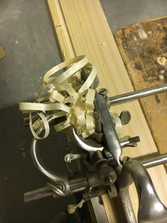
Durante la lavorazione si renderà necessario liberare spesso la gola dell’ incorsatoio dai trucioli che vengono espulsi verso l’alto, a meno che non si stia usando il deflettore. Ricordatevi che gli incorsatoi si intasano spesso. È importante controllare spesso anche lo stato del canale che si sta creando che dovrebbe risultare con le pareti ed il fondo perpendicolari e dritti tra loro. Se il canale venisse con il fondo non in piano o con le pareti storte risulterebbe in seguito difficile inserire l’eventuale pannellatura.

La scelta della lama è importante. Il canale si genera della stessa larghezza e forma del tagliente della lama. Solo se vogliamo creare una battuta nel legno si deve scegliere una lama di larghezza maggiore della battuta che vogliamo creare. Se dobbiamo lavorare traverso vena ci si può aiutare mediante gli spurs, come accennato sopra. Va comunque detto che un normale coltellino da tracciatura può fare lo stesso lavoro degli spurs.
Durante la realizzazione del canale possiamo incontrare alcune difficoltà legate più che altro alla venatura contraria o alla presenza di nodi. L’ incorsatoio tenderà ad impuntarsi e a strappare le fibre. In tali evenienze può essere utile incidere l’intersezione tra le pareti ed il fondo del canale con un coltellino o una sega o, se il canale è appena accennato, definire la sagoma con un truschino, meglio se di quelli dotati di rotella tagliente. Così facendo si recidono le fibre e si facilita l’azione di piallatura. Un’altra accortezza è quella di verificare che ci sia parallelismo tra la guida parallela e la slitta. Meglio sarebbe che la distanza tra le guide nella parte anteriore sia leggermente inferiore (circa 1 mm.) rispetto alla distanza nella parte posteriore. Se così non fosse infatti la piallatura diverrebbe molto difficile se non addirittura impraticabile. Per ovviare al problema si può tenere allentata la vite che tiene la parte posteriore.
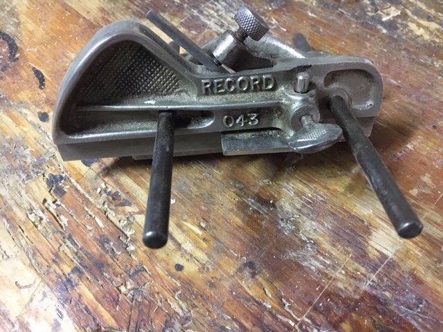
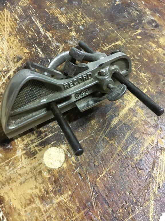
La Record 043 è un incorsatoio di ridotte dimensioni, molto maneggevole ed utile per lavori di piccola entità e su piccoli pezzi. Per quanto riguarda le caratteristiche ed il funzionamento è del tutto simile agli incorsatoi di maggiori dimensioni, come ad esempio il Record 044.
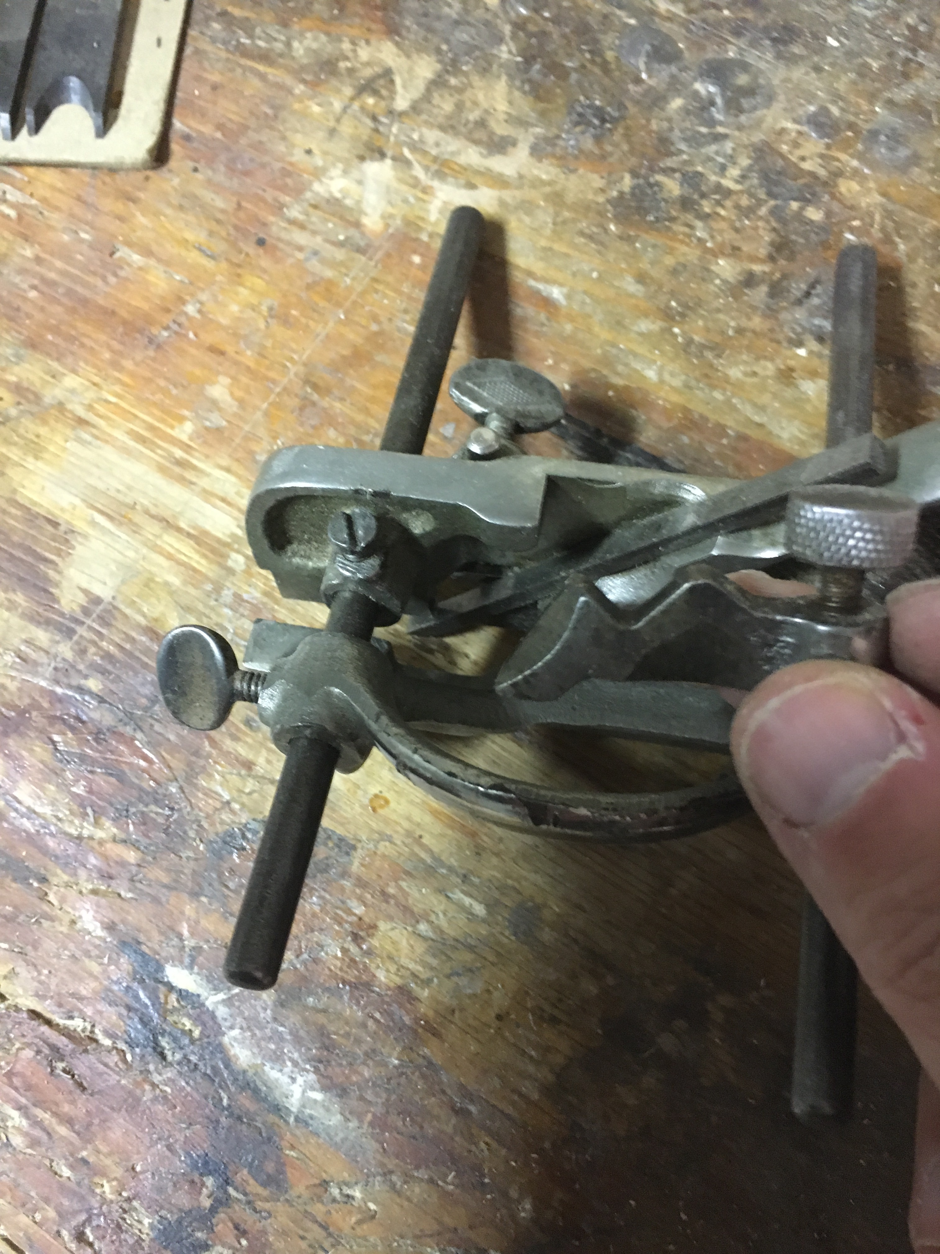
Monta lame più strette e non provviste di scanalatura visto che il sistema di aggiustamento della profondità di taglio avviene agendo manualmente e direttamente sulla lama stessa che viene bloccata al corpo della pialla mediante una sorta di lever cap ad incastro ed una rotella che agisce premendo sul lever cap stesso. Soprattutto rispetto al sistema di bloccaggio della lama ed alla guida parallela questi modelli si differenziano dalla Record 050 di cui ho parlato sopra.
Usare l’incorsatoio, indipendentemente dal modello utilizzato, è estremamente piacevole. Una volta acquisita familiarità con l’impostazione dell’attrezzo, che sicuramente è il passo più difficile, sarà possibile apprezzare appieno il potenziale e l’efficacia di questo strumento di cui non si potrà più fare a meno.
———————————————————————————————————————————
In the large panorama of the planes there are some that I would define special because they differ a lot from the typical shape of the plane and in how they work. Among these we have already talked about the router plane, a particular type of plane useful for woodworking such as leveling the bottom of a housing dado. In this post I would like to talk about another type of plane: the plough plane (plow plane in USA). This tool is often mistakenly referred to as a multi-function combination plane or, as some of the period catalogs reported, even as a universal plane, able to perform any planing work. Stanley 55 was an example. In reality, only with some particularly complex plough plane models it is actually possible to do a lot of work which however, in practice, is often not very effective and difficult to set up, as well as not being particularly performing. Referring then to the simpler versions of the plough plane (the more specific ones for particular works), these can essentially do two types of work in the wood: grooves along the grain (and sometimes across the grain) and rebates in the wood. In woodworking by hand this plane can create grooves in which it is possible to insert panels or glass (such as door and window panels or the back of some furniture), or bottom drawers, or make some dente canale joints (using the special blades useful to form the interlocking tooth and channel) and for various other uses where we need to obtain a groove where to house something. In the past it was a very widespread tool but today some power tools (such as the bench saw and the router) have actually replaced it, making the same work and faster. But I find that this tool still has its value in woodworking for the effectiveness and precision of working. At first sight its shape can intimidate a little. Its use is not very simple and it takes time to be set up properly and before you can make it work. But once you understand how it works, you immediately realize what a small engineering masterpiece it is. Even today, the few modern producers of this tool build the plough plane, tracing the original model, with very few variations, reflecting the goodness of its construction. The historic makers of this type of plane stopped to build it many decades ago but, as mentioned, some modern manufacturers, such as Veritas, offer an excellent plough plane even if the price is not properly cheap. Historical brands are, as always in this field, Record and Stanley. These two manufacturers have in the past produced many types of plough planes but four models on all have become very common. These are the Records (and Stanley) 043 and 044 and, among the so-called combination plough planes, the Stanley 45 and the Record 050. This, among the types in metal. The very first models of plough planes were however built of wood and among the most famous brands we can include Marples, Mathieson, and Sandusky, just to name a few. The purchase of a used ploughplane should therefore be directed towards the mentioned producers. The plough plane generally works along the grain of the wood, therefore along the side, creating grooves that are straight and parallel to the piece we are working on. Some particular types of plough planes can, however, also work across the grain. In fact, as we will see later, even some common plough planes can work across the grain if they have spurs, small cutting edges able to cut the fibers through the grain allowing to work also on this type of grain.
Wooden plough planes
The first plough planes were made of wood, with some inserts in brass, steel and other materials. In the past some models were made in very expensive materials, looking fancy, searching more to the aesthetics than to their actual efficiency. The dimensions are very generous and of considerable weight, often superior to the metal plough planes. The shape and how they work, however, are very similar to the most modern metal planes. Despite the weight and size not very light, their use is always very pleasant (as with all wooden planes) and this is essentially due to the ease of sliding of the wood on the wood. The oldest models were with a guide with wedged stems. The system worked well but the strong stresses to which the wedges were subjected made it so that sometimes they could slip from the guide. To solve the problem was created a guide provided with a screw stem system. In these models stability and precision are greater. As with all wooden planes the blade is inserted into the mouth of the plough plane body and held in place by a wedge. Many models have a depth stop and a cutting edge to cut the fibers across the grain. The shape of the blade is thicker at the base and tapered at the top. This to create an opposite slope against the strength of planing work and prevent the moving of the blade. The peculiarity of some blades is also the presence of a groove on the back of the blade in a central position that allowed it to be housed. The use of this type of planes requires a certain strength, well compensated by the pleasure during use. Nowadays very few producers build wooden plough planes. It is therefore advisable to look into the vintage market where there are many brands among which Marples and Sandusky stand out. A valid alternative, if you have the skills, is to dedicate yourself to self-construction.
Metal plough planes
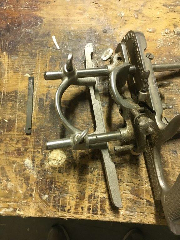
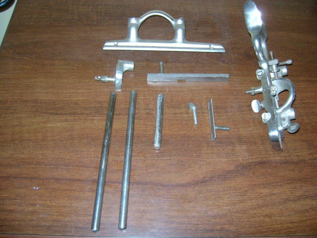
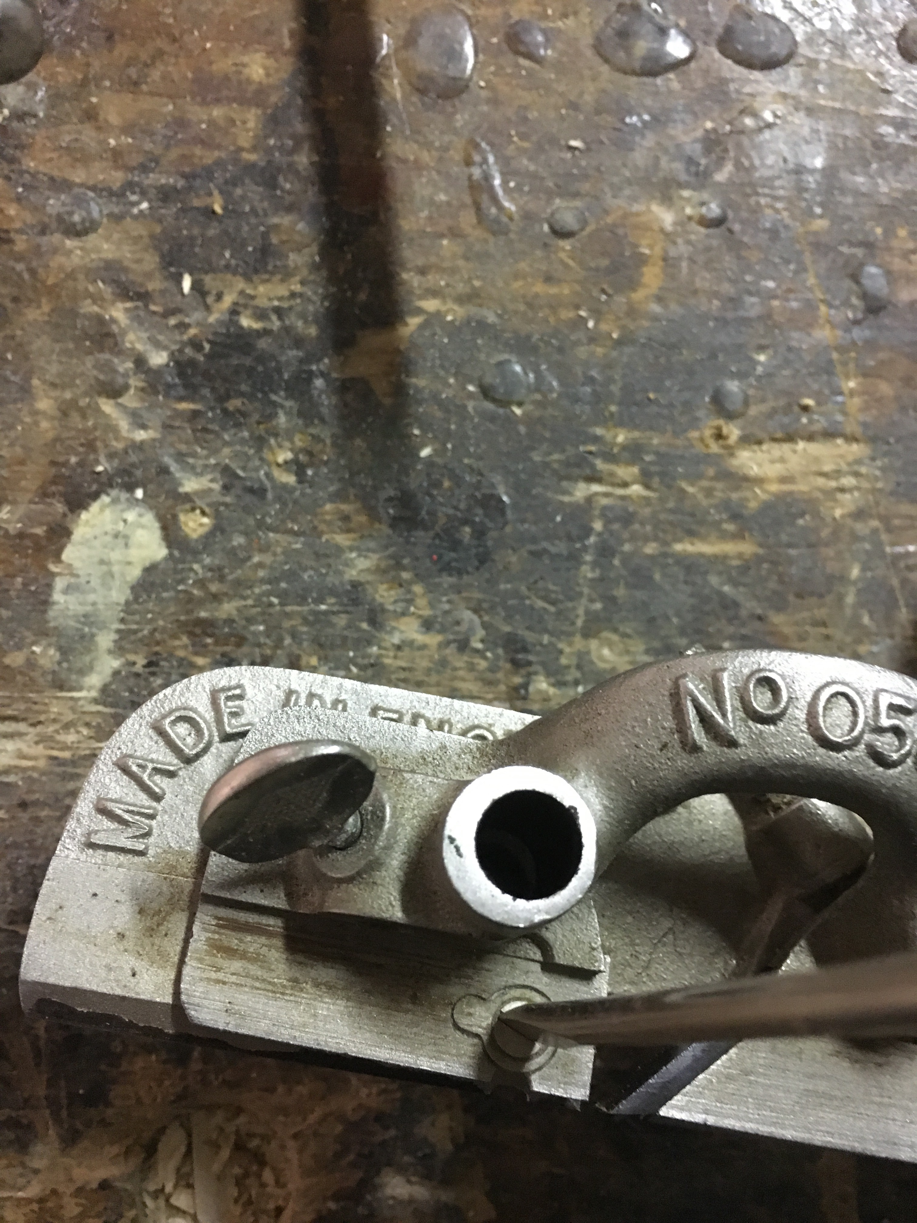
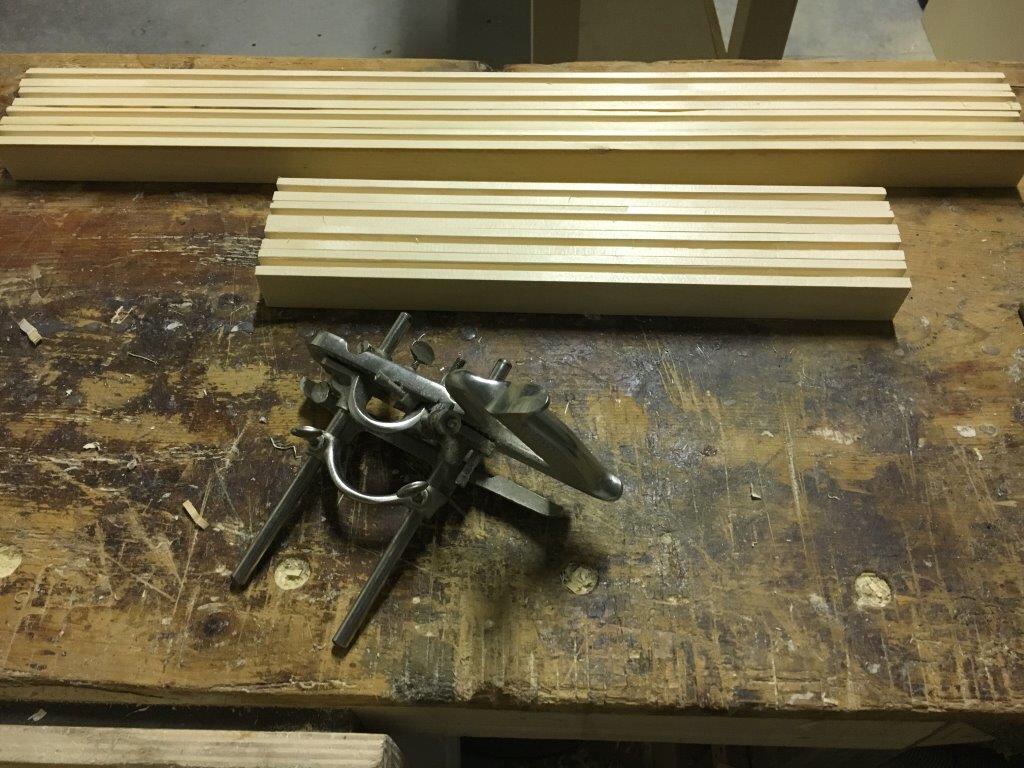
The metal plough planes are the ones I know best and on which I can then spend a few words more. In fact, I own a Record 043 and a Record 050. The metal plough planes are obviously more recent than those made of wood. The two historical brands as mentioned above are Record and Stanley, which have continued to produce them at least until the middle of the last century. At first sight, the plough plane is difficult to understand. Briefly, it can be said that it consists of a metal body on which a blade is inserted and laterally a fence and a parallel guide which slides on two bars which are inserted into the plane body itself. The tool is completed with a depth stop, two blades to cut across the grain and a chip deflector. This very briefly. Now let’s see in detail the various parts of a plough plane, specifically a multiplane model Record 050A plough plane, and the Record 043. Basically the Record and Stanley models 043 and 044 are very similar, certainly simpler and to say of many even more effective of multiplanes.
Record 050A (improved combination plane)
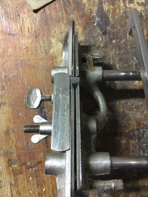
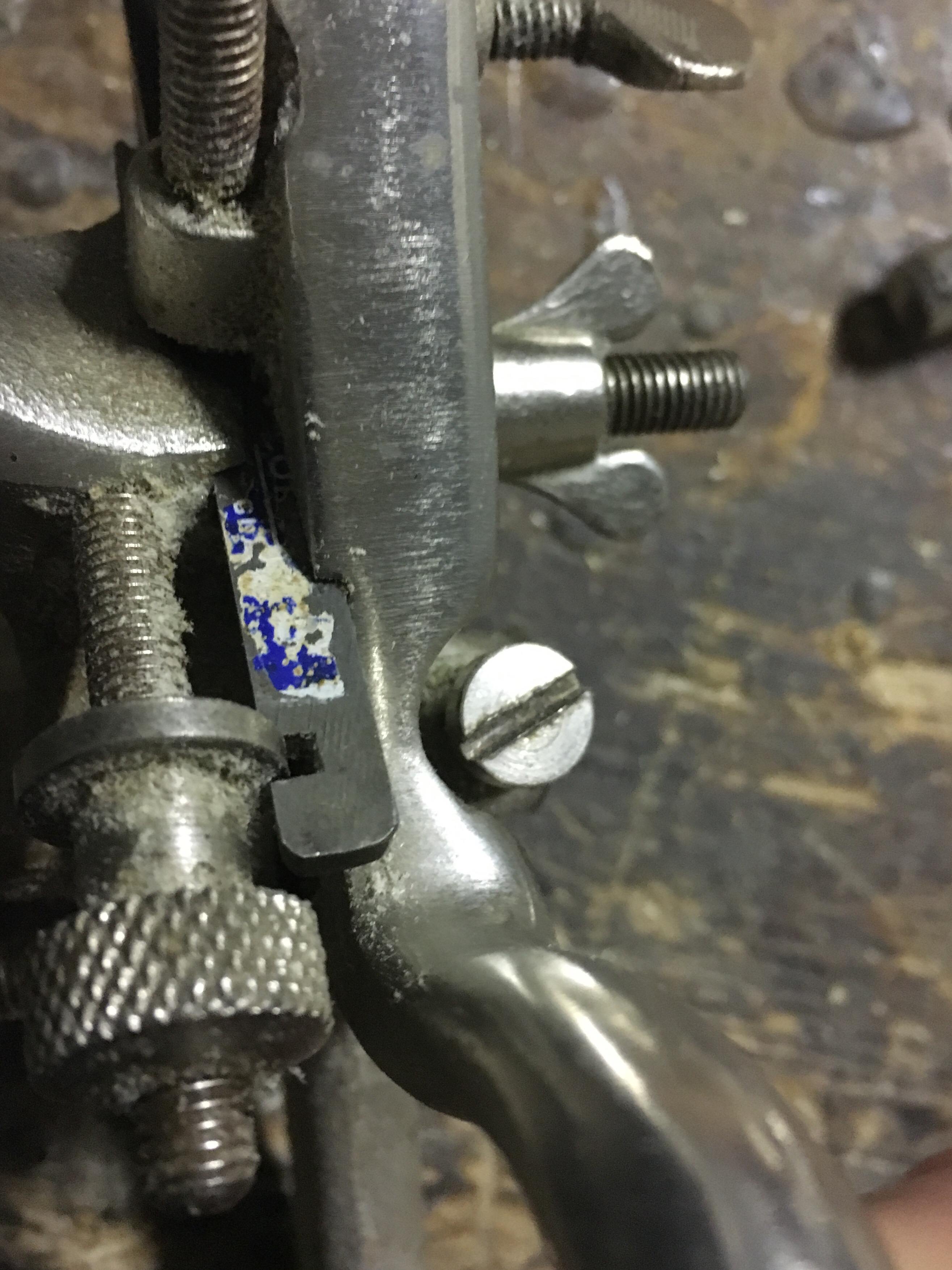
A) main stock in metal where the handle is obtained in the body itself (without any covering as in the most common Record models) or covered in wood or plastic in other models. The recess where the blade is inserted is formed in the main body. In the body there is a slot in which the blade depth adjustment wheel is inserted and works. There is also a shoulder (sled) that will form the parallelism with the sled on the side of the plane. In the plane body there are also various housings for the fence bar rods, the depth gauge, the shaving deflector, and the various locking screws, such as the one which allows the downward pressure of the blade.
B) the sliding section which connects to the plane body by a wing screw. The slide laterally closes the blade against the plane body and is provided with a handle. A screw on the back of the slide consolidates and maintains the parallelism of the slide with the plane body.
C) the fence that allows to keep the plough plane perpendicular and always at the same distance to the side of the piece where the groove is being created. The fence is inserted and slides on two parallel bar rods that are inserted in the plane body. The fence locks on the bars using wing nuts. In the main stock, the metal bars are blocked by screws. At the fence it is possible to screw a hardwood piece of wood so as to increase the depth of support of the guide. It is a good rule, before use, to lubricate both the slide of the plough plane and the wooden base so as to facilitate the planing action.
D) the depth gauge is a metal base (removable) that allows the predetermination of the groove depth. It flows on a metal cylinder and is blocked by a wing screw. Operation is simple. During the planing action the plough plane goes down as it progresses into the groove. When the base will come into contact with the workpiece this will not allow the blade to cut further.
E) the shaving deflector is a removable element that, once inserted, allows the lateral expulsion of the shavings instead of upwards.
F) the spurs are two small wheels equipped with a cutting edge that can be used to cut the fibers when working across the grain. Using a screwdriver it is possible to loosen the screw that keeps them in the retracted position and turn them so that the small blade protrudes. Before using them, the screw must obviously be tightened again.
G) to support the two narrower blades, remove the sliding section and insert the supplied cutter clamping bracket into the rear bar of the fence.
The metal plough planes were supplied with some blades of various sizes so as to be able to adapt to the various processes. The most common sizes are: 3 mm; 4.5 mm; 6 mm; 8 mm; 9.5 mm; 12.5 mm. The most commonly used blades were those with a ploughing shape, but the cobination plough planes were provided with many more blades of different shapes and sizes (tonguing, beading, ploughing, rounding) so as to be able to practice various processes and multiple mouldings (the Record 050A was provided with 17 cutters).
Sharpening
The plough plane work with the blade edge facing downwards. Usually the blades are sharpened at 30 degrees but you can also find sharpening between 25 and 30 degrees. The important thing is to never create a sharpening where the cutting edge is lower than the end of the same, otherwise it would be impossible to make the blade work in the wood. As mentioned, the blades are provided with a recess which allows the insertion of the depth adjustment wheel. Compared to the common blades of the planes the blades of the plough planes are very narrow and this, if on one hand allows a quick sharpening, on the other requires to pay special attention to create a sharp straight edge, especially if we sharpen freehand. If the cutting edge is skewed, this will affect the bottom of the groove. The woodworker Paul Sellers also recommends of slightly chamfering the sides of the blades (not near the cutting edge), so as to favor the planing action. The old blade models were already produced with a back of the blade narrower than the other, practically giving the blade a trapezoidal shape. Before sharpening the cutting edge, always check the flatness of the back of the blade, paying attention that it is straight or slightly concave. A possible convexity should instead be corrected through a clamping of the highest points and with the help of a lever in counterpressure. The sharpening can be done on diamond or other types of stone or on abrasive paper, turning the bevel downwards and holding the blade with the thumb and middle fingers and the index placed on the back. During the freehand sharpening the fingers of the other hand can support the movement allowing more control. Finally you can proceed to lapping with the abrasive paste on the strop as seen in the post on sharpening.
Using the plow plane Record 050A
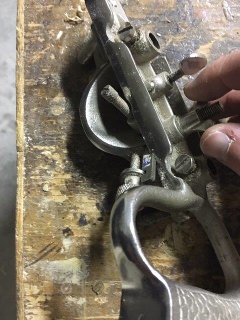
1) Loosening the wing screw on the side of the plane body loosens the sliding section so as to make room for inserting the blade. The blade is inserted from below, with the cutting edge facing downwards and inserted into the special recess created in the plane body. The recess in the blade is used to insert the wheel that adjusts the depth of the blade. Retighten the wing screw and tighten the screw above the blade of the plough plane. The blade must be tightened between the plane body and the sliding section but not to the point where the depth wheel does not work. At the beginning of processing the blade protrusion must be minimal.
2) Insert the fence on the left side of the pkane body (if right-handed) through the bar rods. The fence and the bars are set to the desired distance from the side of the work piece and then tighten the screws of the guide and the sliding bars.
3) Insert the shaving deflector (optional) and the depth stop in the appropriate housings and tighten with the wing nuts. The depth gauge is adjusted with the help of a ruler or other measuring instrument. The depth stop works as mentioned above.
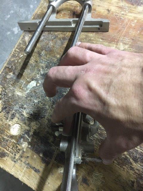
4) Keeping the tool perpendicular to the piece of wood to be worked, the right hand will push the tool forward and the other hand will support the fence keeping it tightly anchored to the piece to be worked. The most important work is made by the hand that supports the guide. The pushing movement must not be too forced as the blade, if sharpened properly, will do all the work.
It starts from the furthest point in front of us at about 10 cm. from the end of the piece to be worked and start with a short and light pass to establish a first light groove in the wood. If we are satisfied with the position of the groove proceed with backward movements always making small passes to establish a first light groove along the entire surface to be worked. As soon as we have defined the walls of the groove we will be able to deepen the blade, obtaining more consistent shavings and therefore greater speed in the work. We proceed until we reach the established size with the stop of depth, which touching the wood, will prevent us from going further. During processing, it will be necessary to release the plough plane throat frequently from the shavings that are expelled upwards, unless the deflector is being used. Remember that plough plane do clog frequently. It is also important from time to time to check the status of the groove being created, which should result with the walls and bottom perpendicular and straight between them. If the groove came with the bottom not flat or with the crooked walls it would then be difficult to insert the eventual paneling. The choice of the blade is important. The groove is created of the same width and shape as the cutting edge of the blade. Only if we want to create a shoulder in the wood should we choose a blade with a width greater than the measure we want to create. If we have to work across the grain, we can help with the spurs, as mentioned above. It should however be said that a normal tracing knife can do the same work as the spurs. During the ploughing of the groove we can meet some difficulties related more to reverse grain or the presence of knots. The plough plane will tend to jam and tear the fibers. In such cases it may be useful to define the intersection between the walls and the bottom of the groove with a small knife or a fine saw or, if the groove is just started, define the shape with a gauge, better those with a cutting wheel. In this way we can separate the fibers and the planing action will result easier. Another precaution is to verify that there is parallelism between the fence and the sliding section (or the plane body). It would be better if the distance between the guides in the opening part is slightly narrower (about 1 mm.) than the distance at the rear end. If this were not so, planing would become very difficult or even impractical. To avoid this problem, the screw that holds the rear part can be kept loose.
The Record 043 is a small plough planes, very handy and useful for small jobs and small pieces. As for the characteristics and operation, it is very similar to the larger plough planes, such as the Record 044. It mounts narrower blades with no grooves, since the cutting depth adjustment system is done manually and directly on the blade itself that is locked to the body of the plane by a sort of interlocking lever cap and a wheel that acts by pressing on the lever cap itself. Especially with respect to the locking system of the blade and parallel guide these models differ from the Record 050 of which I spoke above.
The creation of grooves with the plough planes, whatever the model used, is extremely pleasant. Once you become familiar with the setting of the tool, which is certainly the most difficult step, you can fully appreciate the potential and effectiveness of this type of tool that you can not do without.

Lascia un commento